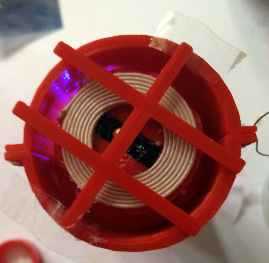
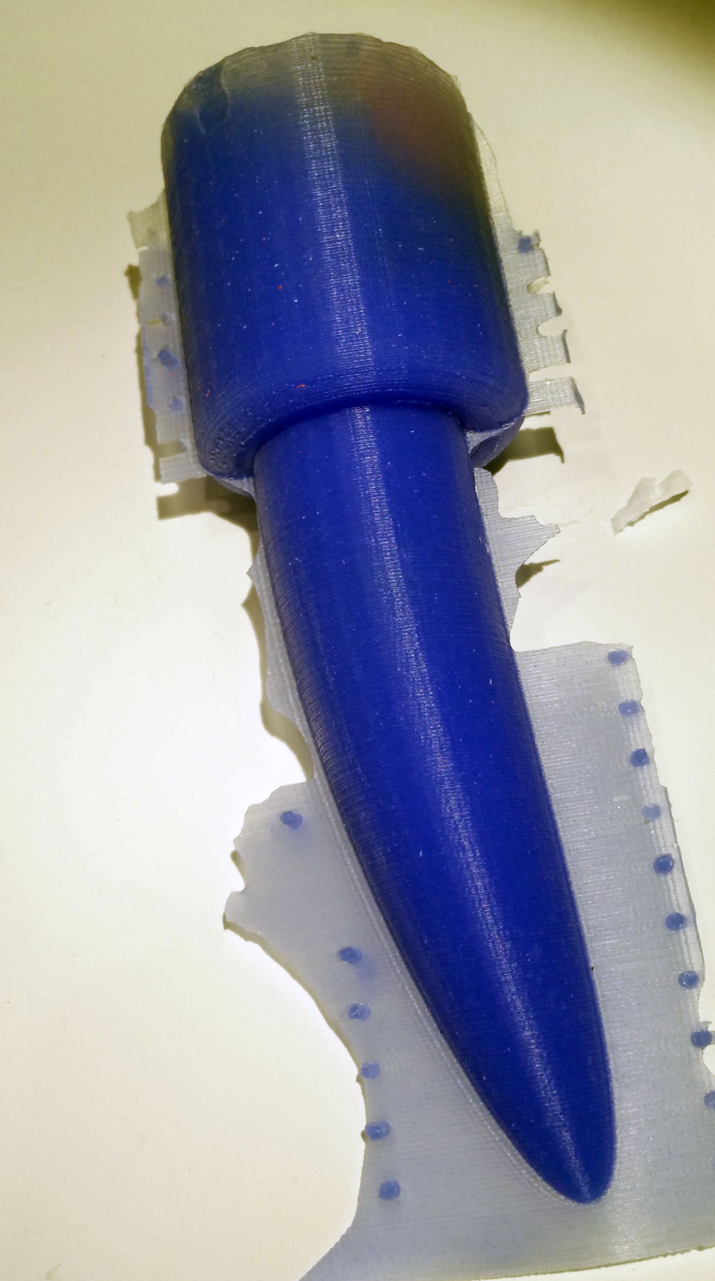
In the first IOT tutorial we have shown how to build a sex toy based on a ESP8266 MCU.
There are two more parts of this tutorial series:
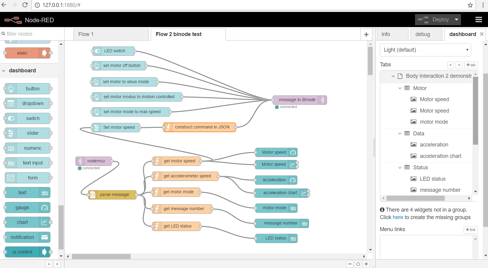
part 3: Node-RED
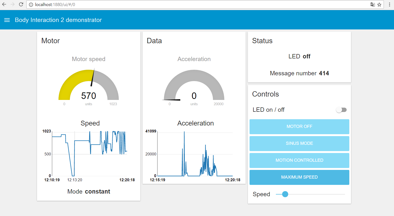
part 4: Building a sex toy dashboard with Node-RED
The ESP8266 is a microcontroller which can connect to the internet. You can write sketches with the Arduino IDE and connect a lot of actuator modules (like vibration motors, displays) and sensors (motion detection).

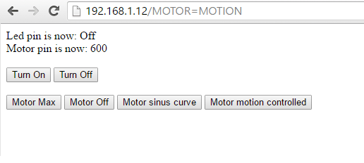
In the first approach a web server was installed on the ESP8266. Control was possible by browsing to the web server, which could be accessed by a computer or smart phone using the same WiFi Access Point (AP).
In this second tutorial we will connect the ESP8266 to the internet and publish and receive data as well as commands by internet.
Protocols
There are some protocols for publishing (sending) data. We use the MQTT protocol which is very fast and suited for short messages. In addition we need a MQTT server. We will send the ESP8266 data to the server. And the ESP8266 can receive data (or commands) from the server. Other services can connect to the MQTT server, too. In this tutorial we will use a MQTT client which can display the sex toy data and send commands to the ESP8266.

Sex toy data exchange format
A big disadvantage of commercial sex toys is their proprietary data exchange formats. Kyle Machutis developed buttplug.io a Cross Platform Framework for Sex Toy Control to overcome this issue.
For this IOT project we will use the JSON format which is a very simple way to exchange data:
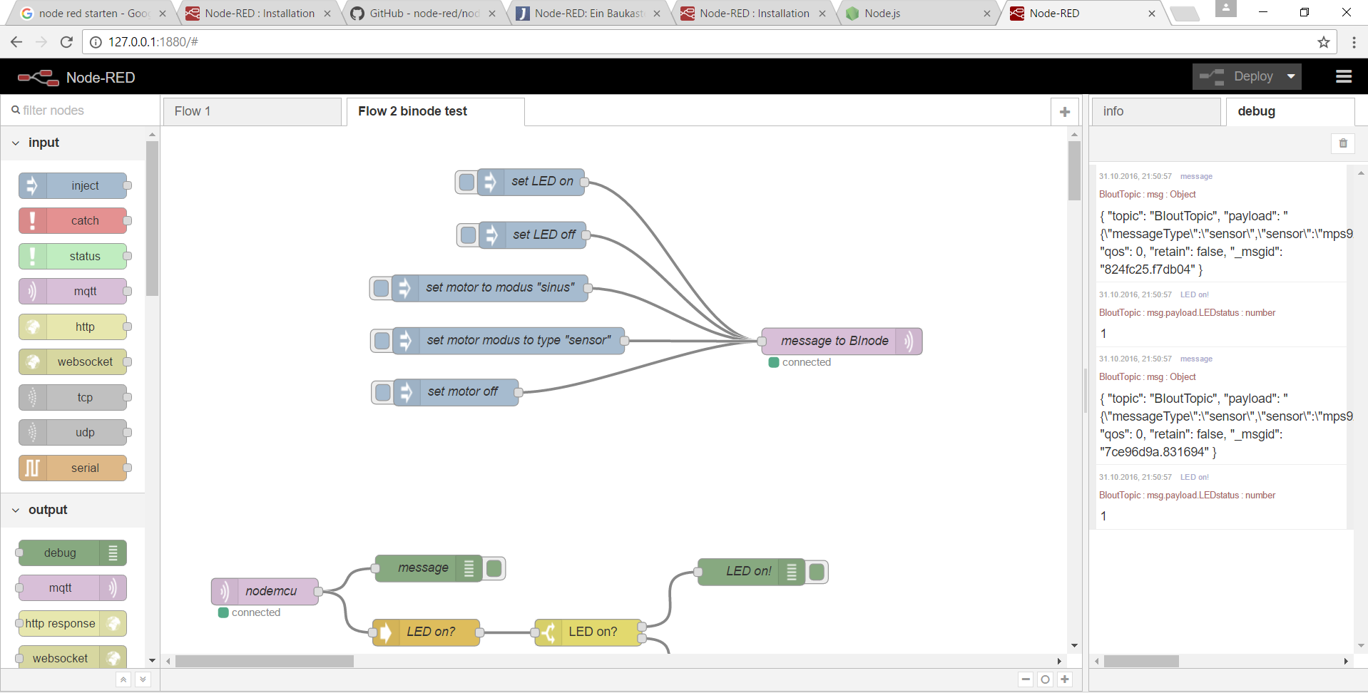
This is an example for the message type “sensor”. It says that the fusioned sensor data of the “mps9250” MPU is 5657, the LED is off (0), the motor is in mode sinus curve (2) and the speed of the vibration motor is 766.
{"messageType":"sensor",
"sensor":"mps9250",
"fusionedData":5675,
"messageNumber":8,
"LEDstatus":0,
"motor1mode":2,
"motor1speed":766}
There are three message types: sensor, execute and message.
- Sensor is for publishing sensor data to everyone who is interested in that.
- Execute is for controlling a specific device, eg for turning the motor on.
- Message sends a text message to specific device. If the deviceID is not given it will be sent to all receivers,
For this project we need the
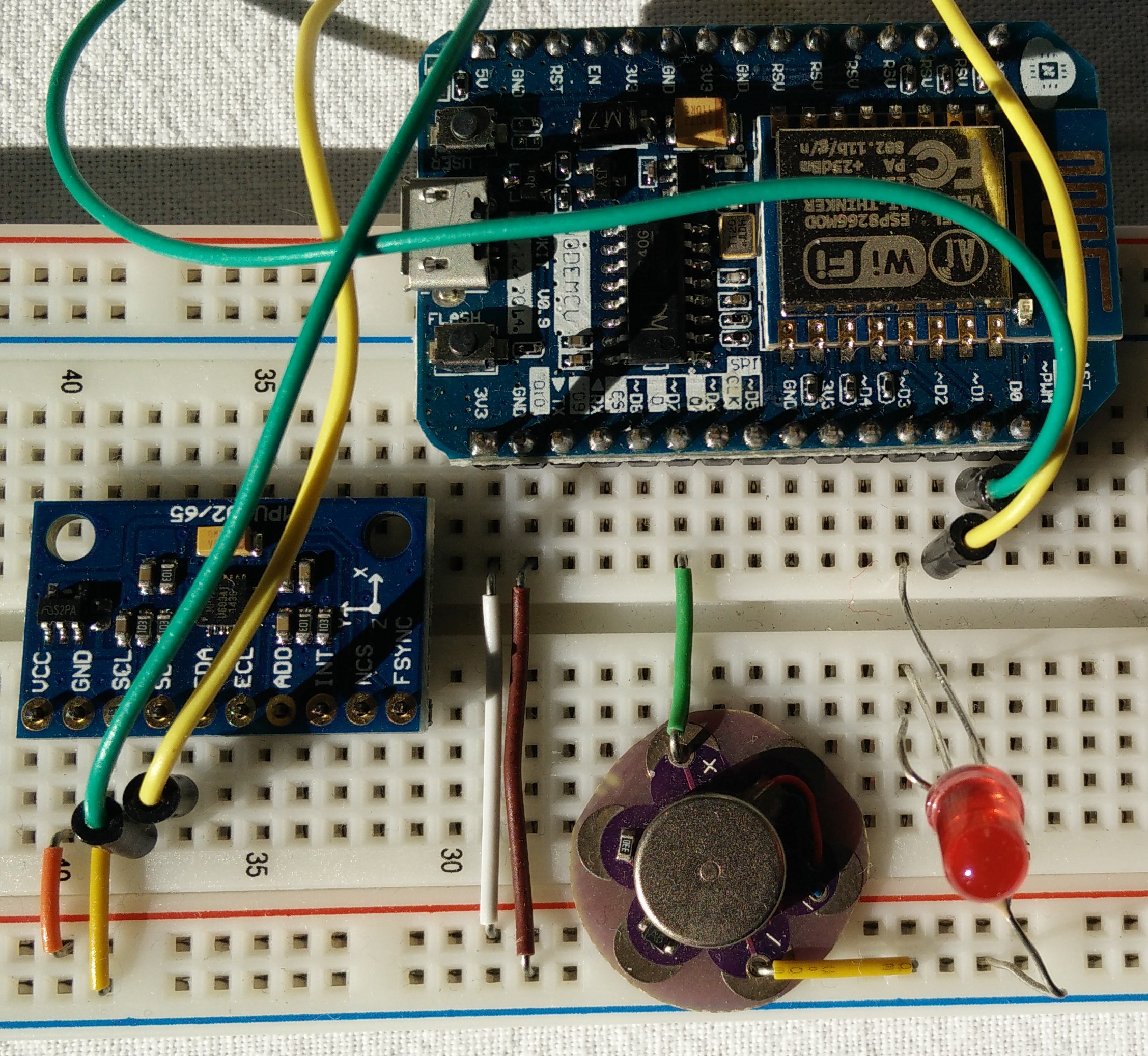
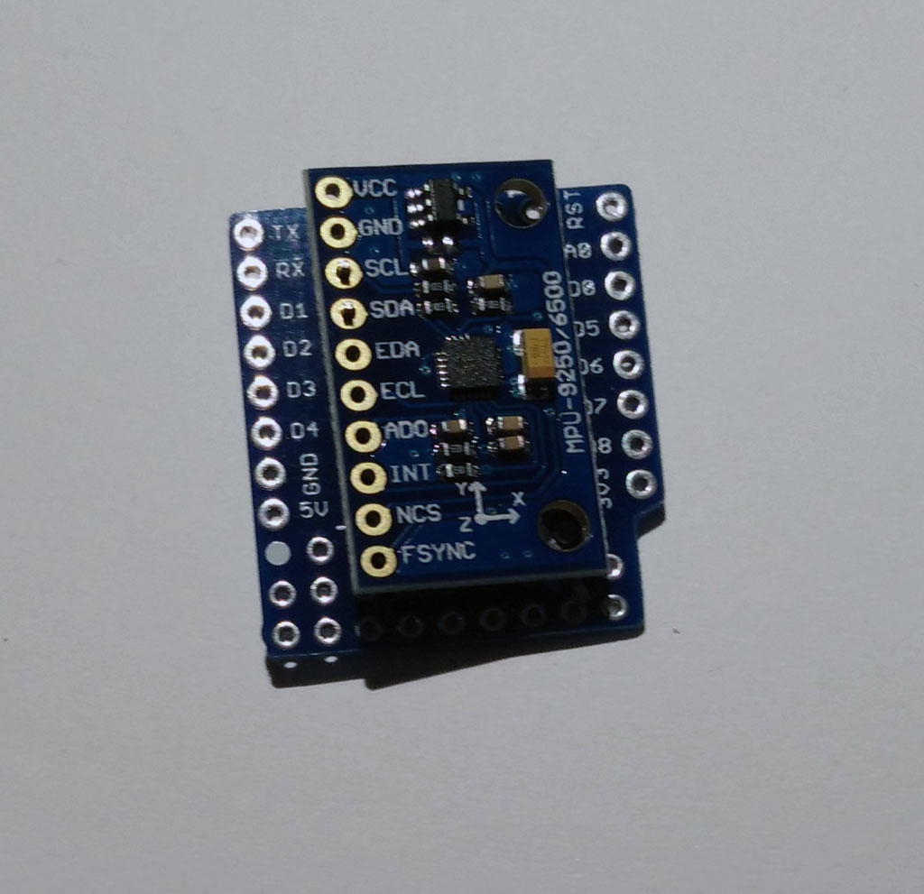
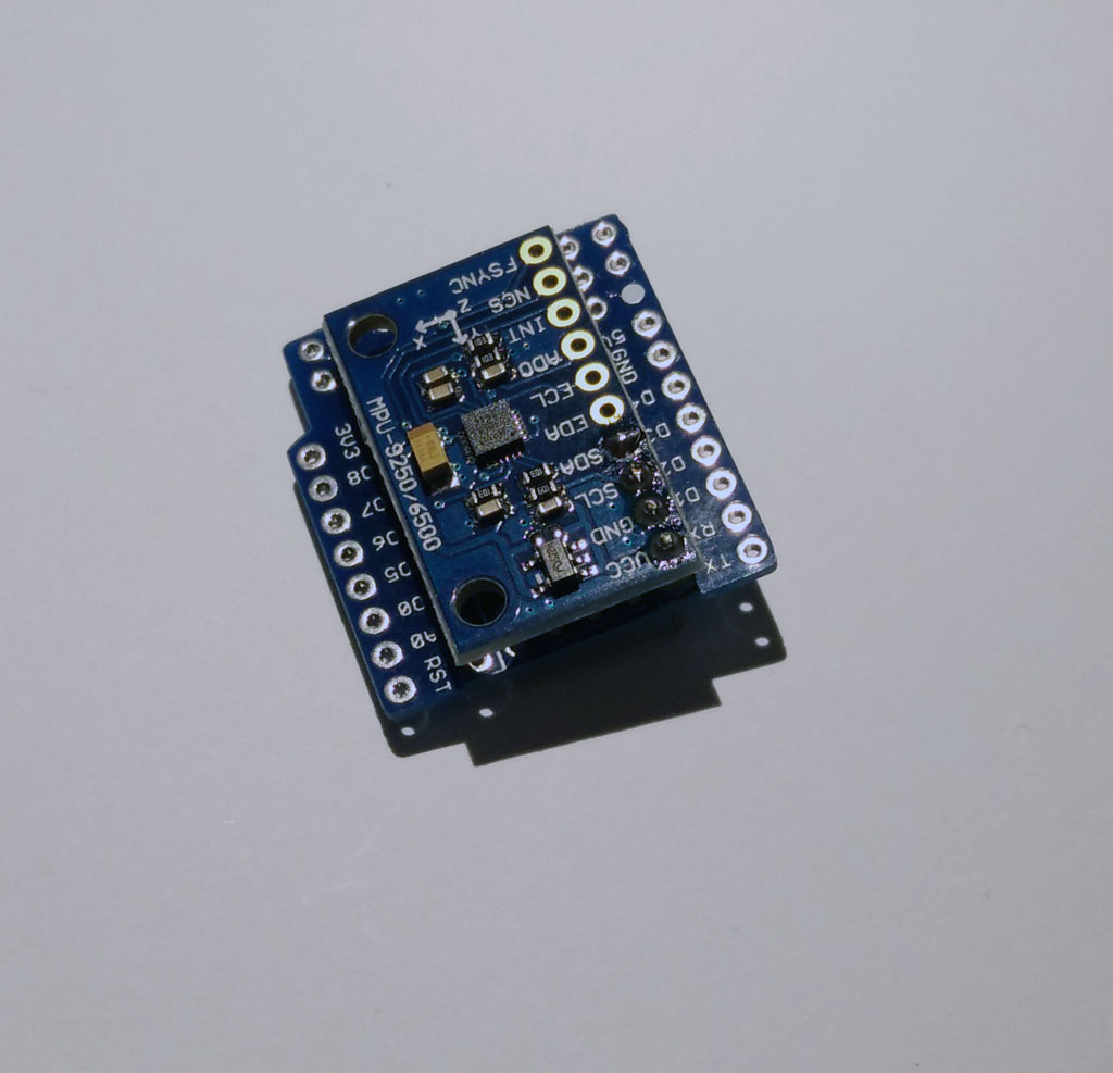
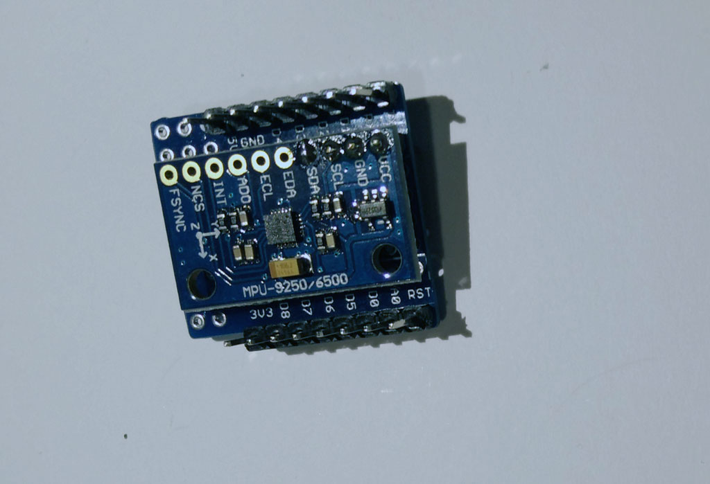
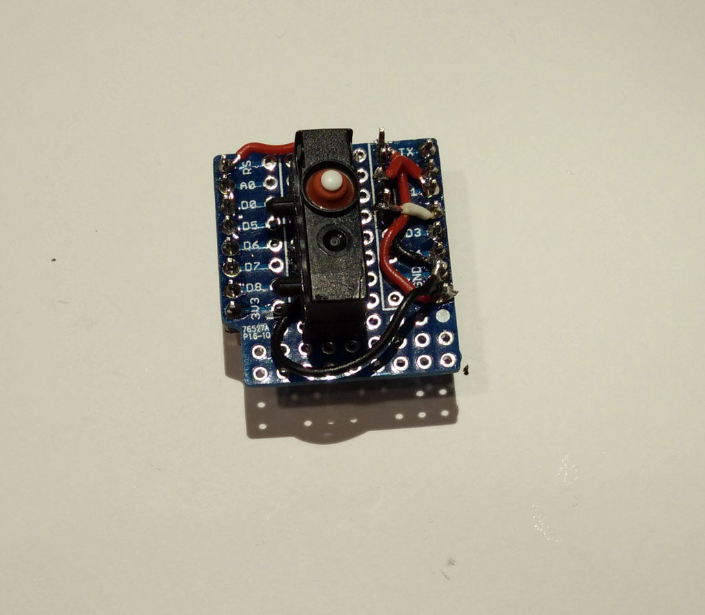
- hardware from part 1 of the IOT project
- the Arduino library JSON for parsing and encoding exchange data
- a library for sending and receiving MQTT data
- the mqtt-spy software to send and receive MQTT messages
- optional: a MQTTserver like mosquitto
Arduino JSON library
There is a great library which can parse and build JSON files. Here is the documentation: https://github.com/bblanchon/ArduinoJson
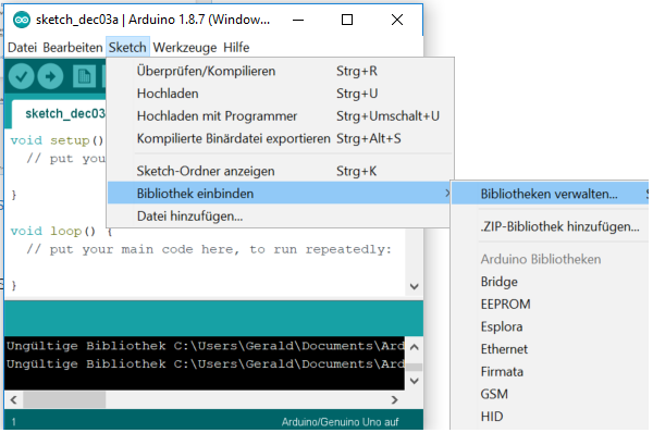
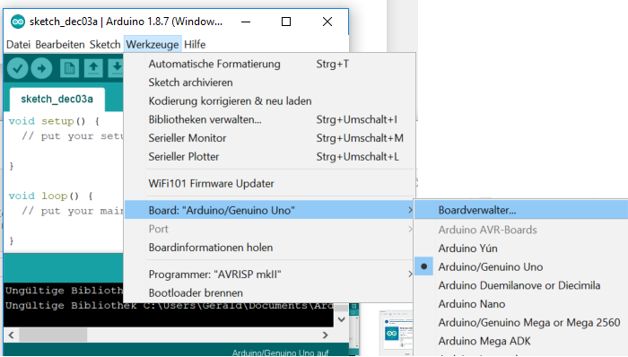
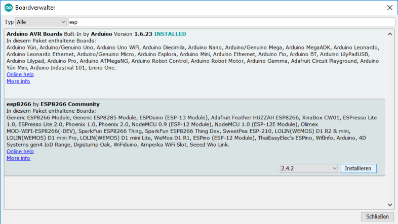
Please go into the Arduino library manager and install the JSON package.
Arduino PubSubClient library
In addition we need a package for sending and receiving MQTT messages. You will find the PubSubClient library in the library manager, too.
Documentation: https://github.com/bblanchon/ArduinoJson
You have to change the maximum length of a message. By default it is only 128. Search for the file PubSubClient.h and change MQTT_MAX_PACKET_SIZE to 1024. On my Win10 system the file is located at
C:\Users\...\Documents\Arduino\libraries\PubSubClient\src\PubSubClient.h
Change the following line:
// MQTT_MAX_PACKET_SIZE : Maximum packet size
 #define MQTT_MAX_PACKET_SIZE 1024
MQTT-SPY software
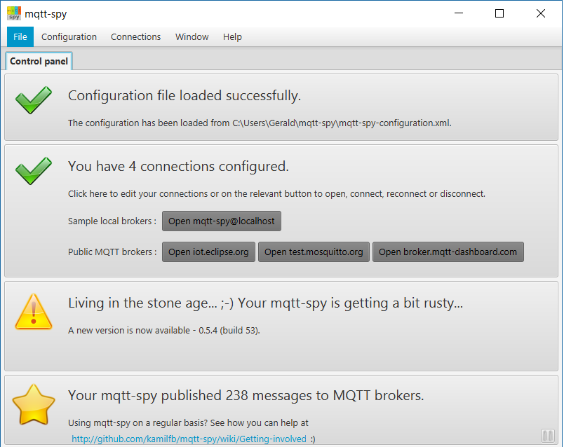
This is an excellent piece of software which can connect to a MQTT server and send and receive messages: mqtt.spy. We use it to test the connection from the ESP8266 to the mosquitto server and for debugging our vibrator toy control software on the ESP8266.
Download from https://github.com/kamilfb/mqtt-spy/wiki/Downloads
If you haven’t your own MQTT server, you can use the Mosquito test server (only for testing, don’t spam them). Start mqtt-spy and connect to “test.mosquito.org”.
Subscription of messages: To receive the messages from the ESP8266 you have to subscribe to a topic. Use the same topic as in the source code, eg. “BIoutTopic”. You have to select the “New”-tab in the subscription, a new window pops up. Enter “BIoutTopic”. Now you receive all messages from the ESP8266.
Publishing messages: In the upper part of the window enter “BIinTopic”. In the “data” field you enter commands which will be sent to the ESP8266. Enter the commands and press “Publish”.
 Try it out. Here are some examples:
JSON data exchange & command examples
Send message:
{
 messageType : "message",
 message : " Hello world!"
 }
Send Command – LED on:
{
 messageType : "execute",
 actuator : "LED",
 actuatorValue : 1
 }
Send command – motor1 modus is set to sinus curve vibration pattern
{
 messageType : "execute",
 actuator : "motor1",
 actuatorMode : "sinus"
 }
Send Command – set motor speed to 1000.
{
 messageType : "execute",
 actuator : "motor1",
 actuatorValue: 1000
 }
Send command – set motor1 off.
{
 messageType : "execute",
 actuator : "motor1",
 actuatorMode: "off"
 }
Message type “sensor”: this is for publishing sensor data of a sex toy (eg. position in 3d space, movement data, vibration pattern in use). These data can be received by other sex toys for vibration adjustment and synchronization of the vibration speed .
{
 messageType : "sensor",
 sensor: "mps9250",
 fusionedData: 10000,
 }
Remark: If it doesn’t work as expected, check the data field of the MQTT software. Paste & Copy doesn’t work as it should be and you may have to remove some redundant “{“-signs.
Code
The code is based on part 1. In the new code functions for publishing and receiving JSON data over MQTT are added.
Receiving and parsing incoming JSON files is done in “callback”. “callback” will be executed whenever a MQTT message comes in.
void callback(char* topic, byte* payload, unsigned int length) {
At first the incoming message is parsed and the result is stored in “root”. Now each entry in the JSON file can be accessed by assigning a new variable to root[entry]:
StaticJsonBuffer<500> jsonBuffer;
 JsonObject& root = jsonBuffer.parseObject(s);
 if (!root.success()) {
 Serial.println("parseObject() failed");
 }
 String messageType = root["messageType"];
Build and publishing JSON files is done in the loop. A JsonObject “root” is created and then each entry in the JSON file is added by an assignment to root eg: root[“messageType”] = “sensor”:
StaticJsonBuffer<500> jsonBuffer;
JsonObject& root = jsonBuffer.createObject();
root["messageType"] = "sensor"; // execute, message, sensor
For producing the JSON file there is “printTo” function. The JSON array of char must be formatted with the snprintf() function and then it can be published.
 root.printTo(outMsg, sizeof(outMsg));
 snprintf (msg,1000, "%s",outMsg);
 mqttclient.publish("BIoutTopic", msg);
Download the zipped and formatted code here: nodemcu-server-mqtt-iot.
In the next part of the tutorial we use Node-RED for visual programming our IOT sex toys.
Here is the complete source code for part 2 of the tutorial.
// bodyinteraction IOT project
// IOT sex toy prototype - control via browser and MQTT
#include <ESP8266WiFi.h>
#include <Wire.h>
#include <PubSubClient.h>
#include <ArduinoJson.h>

#define MPU9250_ADDRESS 0x68
#define MAG_ADDRESS 0x0C

#define GYRO_FULL_SCALE_250_DPS 0x00
#define GYRO_FULL_SCALE_500_DPS 0x08
#define GYRO_FULL_SCALE_1000_DPS 0x10
#define GYRO_FULL_SCALE_2000_DPS 0x18

#define ACC_FULL_SCALE_2_G 0x00
#define ACC_FULL_SCALE_4_G 0x08
#define ACC_FULL_SCALE_8_G 0x10
#define ACC_FULL_SCALE_16_G 0x18

const char* ssid = "ALICE-WLAN";
const char* password = "36s69c3756a65";
const char* mqtt_server = "test.mosquitto.org";

int ledPin = 0; // NodeMCU pad D3 = GPIO 0
int motorPin= 13; // NodeMCU pad D7 = GPIO 13
double sinusValue=0;

// define constants for four different vibration modes
const int offMode=0;
const int maxMode=1;
const int sinusMode=2;
const int motionMode=3;

int motorMode =offMode; //current mode
int motionVector = 0; //current fusioned motion
// Acceleration in x,y and z direction at t(ime)=1 and time=0
// Geroscop data
int16_t ax,ay,az,ax1,ay1,az1,gx,gy,gz,gx1,gy1,gz1;
int valueMotor; //vibrator motor speed 0-1023

WiFiServer server(80);

WiFiClient espclient;
PubSubClient mqttclient(espclient);
char msg[512];
char outMsg[512];

bool requesting=false; // is there a request eg button pressed on webpage

//timing of mqtt messages
long now=0;
long lastMsg = 0;


int value = 0;
int valueLED = LOW;

// This function read Nbytes bytes from I2C device at address Address.
// Put read bytes starting at register Register in the Data array.
void I2Cread(uint8_t Address, uint8_t Register, uint8_t Nbytes, uint8_t* Data)
{
// Set register address
Wire.beginTransmission(Address);
Wire.write(Register);
Wire.endTransmission();

// Read Nbytes
Wire.requestFrom(Address, Nbytes);
uint8_t index=0;
while (Wire.available())
Data[index++]=Wire.read();
}

// Write a byte (Data) in device (Address) at register (Register)
void I2CwriteByte(uint8_t Address, uint8_t Register, uint8_t Data)
{
// Set register address
Wire.beginTransmission(Address);
Wire.write(Register);
Wire.write(Data);
Wire.endTransmission();
}


// Return the response /generate webpage
void generateWebpage(WiFiClient espclient) {
espclient.println("HTTP/1.1 200 OK");
espclient.println("Content-Type: text/html");
espclient.println(""); // do not forget this one
espclient.println("<!DOCTYPE HTML>");
espclient.println("<html>");

espclient.print("Led pin is now: ");

if(valueLED == HIGH) {
espclient.print("On");
} else {
espclient.print("Off");
}

espclient.print("
Motor pin is now: ");
espclient.print(valueMotor);

espclient.println("

");
espclient.println("<a href=\"/LED=ON\"\"><button>Turn On </button></a>");
espclient.println("<a href=\"/LED=OFF\"\"><button>Turn Off </button></a>

");
espclient.println("<a href=\"/MOTOR=MAX\"\"><button>Motor Max </button></a>");
espclient.println("<a href=\"/MOTOR=OFF\"\"><button>Motor Off </button></a>");
espclient.println("<a href=\"/MOTOR=SINUS\"\"><button>Motor sinus curve </button></a>");
espclient.println("<a href=\"/MOTOR=MOTION\"\"><button>Motor motion controlled </button></a>
");
espclient.println("</html>");
}

// function callback is executed when a Mqtt message comes in
// - prints mqtt message
// - parse JSON file
// - execute commands
void callback(char* topic, byte* payload, unsigned int length) {
Serial.print("Message arrived [");
Serial.print(topic);
Serial.print("] ");
char s[length];
for (int i = 0; i < length; i++) {
Serial.print((char)payload[i]);
s[i]=payload[i];
}
StaticJsonBuffer<500> jsonBuffer;
JsonObject& root = jsonBuffer.parseObject(s);
if (!root.success()) {
Serial.println("parseObject() failed");
}
String messageType = root["messageType"]; //sensor, execute , message
String targetDeviceID = root["targetDeviceID"];
String actuator = root["actuator"];
int actuatorValue = root["actuatorValue"];
String actuatorMode = root["actuatorMode"];
String message = root["message"];
Serial.print("messageType: ");
Serial.println(messageType);
Serial.print("actuator: ");
Serial.println(actuator);
Serial.print("actuatorValue: ");
Serial.println(actuatorValue);

// print message
if (messageType=="message") {
Serial.print("Incoming message: ");
Serial.println(message);
}
// LED commands
if (messageType=="execute"&&actuator=="LED"&&actuatorValue==1) {
Serial.println("LED on received");
digitalWrite(ledPin, HIGH);
valueLED = HIGH;
}
if (messageType=="execute"&&actuator=="LED"&&actuatorValue==0) {
Serial.println("LED off received");
digitalWrite(ledPin, LOW);
valueLED = LOW;
}
// set modes commands
if (messageType=="execute"&&actuator=="motor1"&&actuatorMode=="off") {
analogWrite(motorPin, 0);
valueMotor = 0;
motorMode=offMode;
}
if (messageType=="execute"&&actuator=="motor1"&&actuatorMode=="sinus") {
motorMode=sinusMode;
}
if (messageType=="execute"&&actuator=="motor1"&&actuatorMode=="motion") {
motorMode=motionMode;
valueMotor=600;
if (valueMotor<500) {valueMotor=500;} if (valueMotor>1023) {valueMotor=1023;}
}
// set motor speed command
if (messageType=="execute"&&actuator=="motor1"&&actuatorValue!=0) {
Serial.println("set motor speed to fixed value");
valueMotor=actuatorValue;
analogWrite(motorPin,valueMotor);
}
// incoming sensor data, adjust motor speed when in motion mode
int fusionedData = root["fusionedData"];
String sensor = root["sensor"];
if (messageType=="sensor"&&sensor=="mps9250"&&motorMode==motionMode) {
if (fusionedData > 5000) {valueMotor=valueMotor+25;} else {valueMotor=valueMotor-10;}
if (valueMotor<500) {valueMotor=500;} //values must be above 500 otherwise the motor is off if (valueMotor>1023) {valueMotor=1023;} // values higher than 1023 are not supported
analogWrite(motorPin, valueMotor); // set motor speed
}
generateWebpage(espclient);
}

// connect to mqtt server
void reconnect() {
while (!mqttclient.connected()) {
Serial.print("Attempting MQTT connection...");
// Create a random client ID
String clientId = "ESP8266Client-";
clientId += String(random(0xffff), HEX);
// Attempt to connect
if (mqttclient.connect(clientId.c_str())) {
Serial.println("connected");
mqttclient.subscribe("BIinTopic");
} else {
Serial.print("failed, rc=");
Serial.print(mqttclient.state());
Serial.println(" try again in 5 seconds");
delay(5000);
}
}
}

void setup() {
Wire.begin();
// connect MPU9265 via i²c bus
// NodeMCU D1 = GPIO5 connected to MCU9265 SCL
// NodeMCU D2 = GPIO4 connected to MCU9265 SDA
Wire.pins(5,4);
Serial.begin(115200);

// Configure gyroscope range
I2CwriteByte(MPU9250_ADDRESS,27,GYRO_FULL_SCALE_2000_DPS);
// Configure accelerometers range
I2CwriteByte(MPU9250_ADDRESS,28,ACC_FULL_SCALE_16_G);
// Set by pass mode for the magnetometers
I2CwriteByte(MPU9250_ADDRESS,0x37,0x02);

// Request first magnetometer single measurement
I2CwriteByte(MAG_ADDRESS,0x0A,0x01);

Serial.begin(115200);
delay(10);

// init LED pin
pinMode(ledPin, OUTPUT);
digitalWrite(ledPin, LOW);

// init motor pin
pinMode(motorPin, OUTPUT);
analogWrite(motorPin, 0);

// Connect to WiFi network
Serial.println();
Serial.print("Connecting to ");
Serial.println(ssid);

WiFi.begin(ssid, password);

while (WiFi.status() != WL_CONNECTED) {
delay(500);
Serial.print(".");
}
Serial.println("");
Serial.println("WiFi connected");

// Start the server
server.begin();
Serial.println("Server started");

// Print the IP address
Serial.print("Use this URL to connect: ");
Serial.print("http://");
Serial.print(WiFi.localIP());
Serial.println("/");

// init mqtt client
mqttclient.setServer(mqtt_server, 1883);
mqttclient.setCallback(callback);
}

void loop() {
if (!mqttclient.connected()) {
reconnect();
}
mqttclient.loop();

// Read accelerometer and gyroscope
uint8_t Buf[14];
I2Cread(MPU9250_ADDRESS,0x3B,14,Buf);

// Create 16 bits values from 8 bits data

// Accelerometer
ax=-(Buf[0]<<8 | Buf[1]);
ay=-(Buf[2]<<8 | Buf[3]);
az=Buf[4]<<8 | Buf[5];

// Gyroscope
gx=-(Buf[8]<<8 | Buf[9]);
gy=-(Buf[10]<<8 | Buf[11]);
gz=Buf[12]<<8 | Buf[13]; // when in "motionMode" the vibration motor is controlled by motion if (motorMode==motionMode) { motionVector=sqrt(pow(ax-ax1,2)+pow(ay-ay1,2)+pow(az-az1,2)); //calculate motion vector // adjust vibration motor speed // if motion vector > 5000 raise speed by 25
// otherwise lover speed by 10
// adjust these constants to your needs
if (motionVector > 5000) {valueMotor=valueMotor+25;} else {valueMotor=valueMotor-10;}
if (valueMotor<500) {valueMotor=500;} //values must be above 500 otherwise the motor is off if (valueMotor>1023) {valueMotor=1023;} // values higher than 1023 are not supported
analogWrite(motorPin, valueMotor); // set motor speed

Serial.print("motionVector: ");
Serial.print(motionVector);
Serial.print(", valueMotor: ");
Serial.println(valueMotor);
delay(200);

// save values
ax1=ax;
ay1=ay;
az1=az;
gx1=gx;
gy1=gy;
gz1=gz;
}

// change vibration motor speed according to a sinus curve
if (motorMode==sinusMode) {
sinusValue=sinusValue+.01;
delay(20);
int sinTmp = ((sin(sinusValue)+1)*.5*(1023-500))+500;
analogWrite(motorPin, sinTmp);
valueMotor=sinTmp;
}

StaticJsonBuffer<500> jsonBuffer;
JsonObject& root = jsonBuffer.createObject();
root["messageType"] = "sensor"; // execute, message, sensor
// execute - send command to other device
// root["targetDeviceID"] = "xxxxx"; //for execute and message message types
// root["actuator"] = "motor1";
// root["actuatorValue"]="222";
// root["actuatorMode"] = "sinus";
// root["command"] = none;
// root["commandParameter1"] ="";

// message - send message to targetDeviceID
// root["message"] = "hello world";

//sensor - for publishing sensor data
root["sensor"] = "mps9250";
// root["time"] = none;
root["fusionedData"] = motionVector;
root["messageNumber"] = 0;
// example for raw data
// JsonArray& rawdata = root.createNestedArray("rawdata"); // x,y,z,roll, pitch better??
// rawdata.add(0, 0); // ax
// rawdata.add(0, 0); // ay
// rawdata.add(0, 0); // az
// rawdata.add(0, 0); // gx
// rawdata.add(0, 0); // gx
// rawdata.add(0, 0); // gx
// rawdata.add(0, 0); // mx
// rawdata.add(0, 0); // mx
// rawdata.add(0, 0); //mx
root["LEDstatus"] = valueLED;
root["motor1mode"] = motorMode;
root["motor1speed"] = valueMotor;

// publish motor speed as mqtt message every 10 seconds
// only when motor in not off
if (motorMode==maxMode||motorMode==sinusMode||motorMode==motionMode) {
now = millis();
if (now - lastMsg > 1000) {
if (!mqttclient.connected()) {
reconnect();
}
lastMsg = now;
++value;
root["messageNumber"] = value;
// publish data as MQTT message in JSON format
root.printTo(outMsg, sizeof(outMsg));
snprintf (msg, 1000, "%s",outMsg);
mqttclient.publish("BIoutTopic", msg);
Serial.print("Publish message every 10 sec: ");
Serial.println(msg);
}
}

// Check if a client has connected to the wifi server
WiFiClient espclient = server.available();
if (!espclient) {
return;
}

while(!espclient.available()){
delay(1);
}

// read the first line of the request
String request = espclient.readStringUntil('\r');
espclient.flush();

// LED on button pressed
Serial.println("hi execute rqeuest");
if (request.indexOf("/LED=ON") != -1) {
requesting=true;
digitalWrite(ledPin, HIGH);
valueLED = HIGH;
root["LEDstatus"] = valueLED;
}
// LED off button pressed
if (request.indexOf("/LED=OFF") != -1) {
requesting=true;
digitalWrite(ledPin, LOW);
valueLED = LOW;
root["LEDstatus"] = valueLED;
}
// set motor to maximum speed button pressed
if (request.indexOf("/MOTOR=MAX") != -1) {
requesting=true;
analogWrite(motorPin, 1023);
valueMotor = 1023;
motorMode=maxMode;
root["motor1mode"] = motorMode;
root["motor1speed"] = valueMotor;
}
// set motor off button pressed
if (request.indexOf("/MOTOR=OFF") != -1) {
requesting=true;
analogWrite(motorPin, 0);
valueMotor = 0;
motorMode=offMode;
root["motor1mode"] = motorMode;
root["motor1speed"] = valueMotor;
}
// motor amplitude controlled like a sinus curve
if (request.indexOf("/MOTOR=SINUS") != -1) {
requesting=true;
motorMode=sinusMode;
root["motor1mode"] = motorMode;
root["motor1speed"] = valueMotor;
}
// motor speed is adjusted by movements (classical "body interaction" interaction pattern)
if (request.indexOf("/MOTOR=MOTION") != -1) {
requesting=true;
motorMode=motionMode;
valueMotor=600;
root["motor1mode"] = motorMode;
root["motor1speed"] = valueMotor;
}


generateWebpage(espclient);

// send outMessage to Mqtt server
if (requesting) {
requesting=false;
if (!mqttclient.connected()) {
reconnect();
}
++value;

root["messageNumber"] = value;
root["motor1mode"] = motorMode;
root["motor1speed"] = valueMotor;

// publish data as MQTT message in JSON format
root.printTo(outMsg, sizeof(outMsg));
snprintf (msg,1000, "%s",outMsg);
mqttclient.publish("BIoutTopic", msg);

Serial.print("Publish message: ");
Serial.println(msg);
}
}

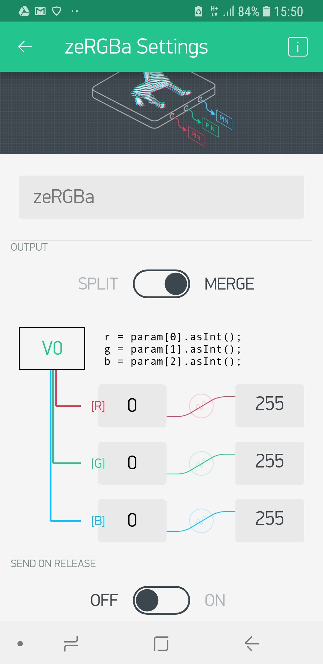
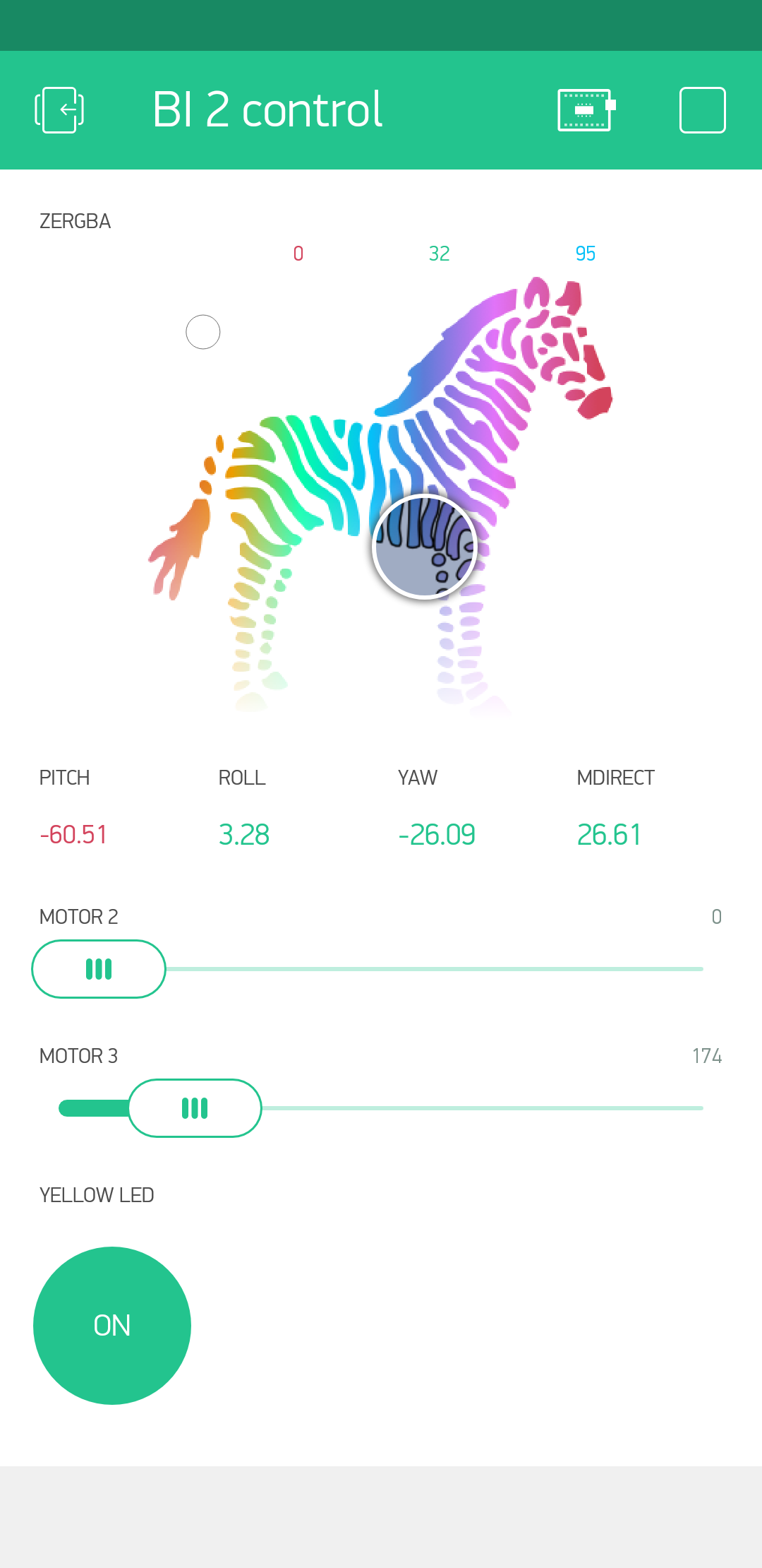 That’s what Blynk is for. Started in 2016 as a kickstarter campaign, they have built a tool which hides a lot of the complexity of the Internet of Things. Blynk consists of the following parts:


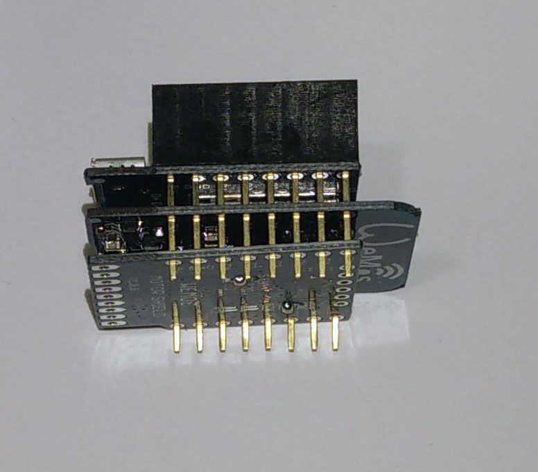


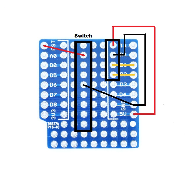
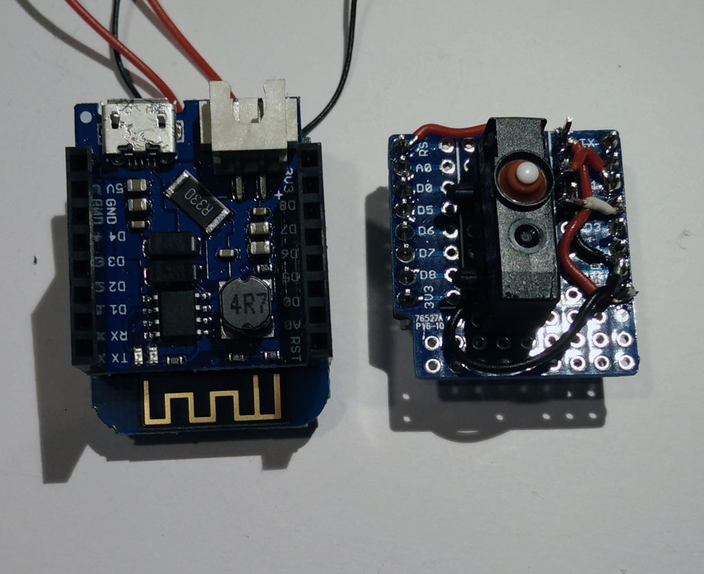


 Now stack the protoytping board on top of the battery shield. And connect the battery.