
The UK-based Startup magazine is looking for the best female startup company. Touchy-Feely is on the short list and you can vote for them. Touchy-Feely develops educational electronic sex toy kits accompanied by workshops on basic and advanced sex toy topics. The founders have committed to building the funniest, most educational and pleasurable DIY electronics and coding kit out there.…
Category: vibrator design
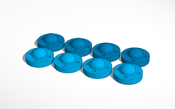
Another ring printed with Elegoo Mars Resin Printer
Since a few month, I own an Elegoo Mars Resin printer. It has UV LCD screen for “printing” each layer. In addition, I have an Elegoo Mercury Wash & Cure machine for a few weeks. These machines are incredibly affordable, they work and have a high resolution. The print space is rather small (120 (L) x 68 x 155 (H)…
The new BI2 black vibrator development board
The new black BI2 board is ready. I have a few assembled boards ready for shipping. Have a look at www.tindie.com
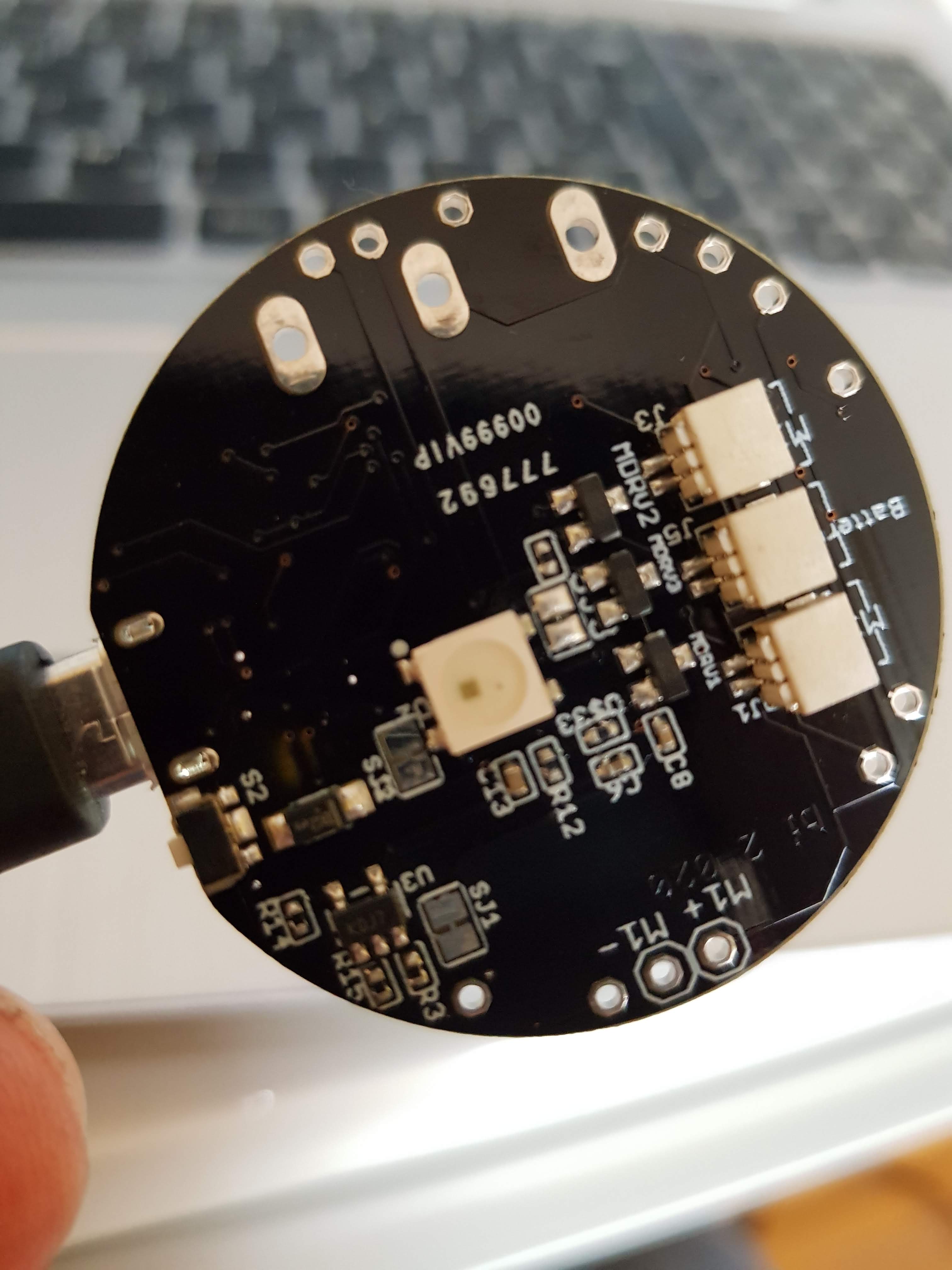
3 JST 1mm plugs (battery, motor 2, motor 3), LED, reset button, M+/M- is for motor 1

JST 1mm plug for motor 1, alternative RESET button
Features
- ESP8266 Microcontroller with WLAN
- MPU9250 (accelerometer, gyroscope)
- LiPo battery charging
- 3 motors can be connected (simple motor driver circuits)
- 1 WS2812B LED – a colourful LED (16 Mill. colours). They are commonly known as Adafruit Neopixel – a strip or a ring of individual programmable LEDs (when use the WS2812B only two motors can be connected)
- design based on the great Adafruit Feather Huzaah ESP8266
- vibration motors and LiPo battery can be easily connected with JST 1mm connectors
- two reset buttons (the button next to the USB connector can be overmolded)
- USB connector for battery charging and code uploading
- programmable with the Arduino IDE or NodeMCU
- white LED for indicating charging
- standard LED (yellow) on GPIO00
- round 40mm diameter

There are 3 free GPIO ports. Standard layout are for driving 2 motors (GPIO 12 = M2, GPIO 13 = M3) and 1 LED (GPIO14). Alternatively you can use 3 motors (GPIO12,13,14) but no LED.
Standard: SJ2 not connected, SJ3 connected
Alternative: SJ2 connected, SJ3 not connected
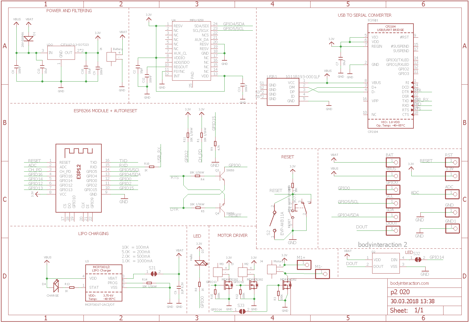
Here is the schematic which is adapted from Adafruit.
References:

BI2 – building a silicone sex toy
Now let’s build the first ESP8266 vibrator. I use the reliable design from this blog post and the new BI2 board. The new BI2 board can be controlled from any smart phone or computer.
As the BI2 board is round there is no need to build a case for the PCB and the LiPo. The easist way is to glue the battery directly on the ESP8266. Connect the battery and one or more vibration motors with the BI2 board.

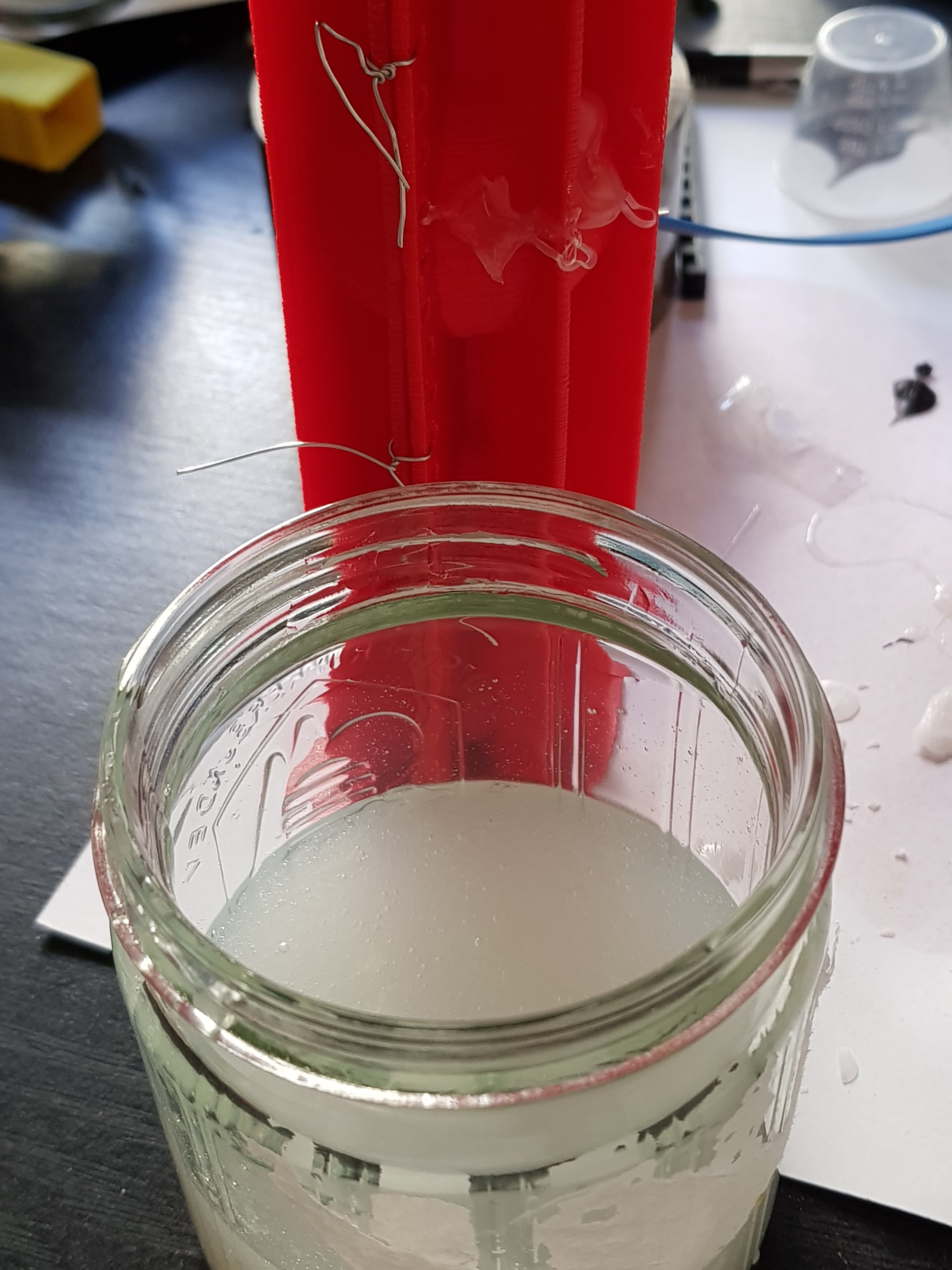
The form consists of two parts which are fastened together with tinker wire. Before you have to insert the board with the vibration motor(s) and the battery. Therefore I used a handle. The handle could be put on top of the form. Then fix a USB connector to the handle. Plug in the BI2 board. Fasten the second half of the form.
Very important: The USB micro connector on the board must be protected from the silicone. When silicone flow between USB plug and connector it will be impossible to pull out the plug. I use wax to seal the USB micro connector. Read more here.

Now pour in the silicone, wait for some hours. And open softely the form.


Remove the overhanging silicone.
Here ist the Link to Tinkercad where you can edit the form and download STL files for your 3D printer: Download from Tinkercad: form, handle. Download ready to print zipped STL files.
Now build YOUR personal sex toy. Here you find the code for the ESP8266 as well as an IOT server application for quantifying your sex and remote control.

Moving dildo with motor driven skeleton
 So far we have used vibration motors for our sex toys. Vibration motors are cheap, powerful, easy to control and robust actuators. That’s why they are part of most sex toys. But what about moving or touching objects. Obviously we need some mechanics, maybe joints and gears? Or is there a simple option? A skeleton?
I realized the idea for using some type of skeleton for moving a dildo when I saw the video of a naked Pleo – one of the best artificial life forms ever.

On www.thingiverse.com you will find more inspiration for using a skeleton to move something. The design is very simple.
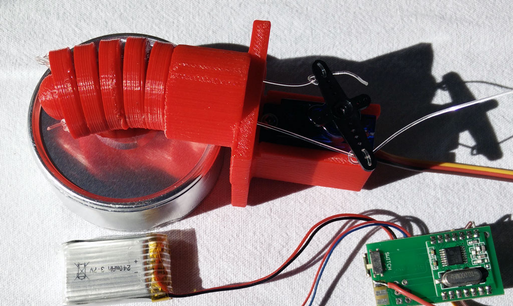
The skeleton is composed of a number of vortexes. The holes are for connecting all vortexes and a servo with a nylon wire or similar.
In addition we need a handle where the vortexes are fastened to. There is also space for a servo. Then use a nylon wire to connect the vortexes with the servo. You can drive the servo with a Arduino development board or you use the body interaction development board as described here.

The servo should turn only 15-30 degree or so. If you use the body interaction development board please copy the following code and upload the code to the board.
#include <TinyServo.h>
// servo control with the body interaction development board using the TinyServo library
// -- adaption of the demo script by
// tylernt@gmail.com's ATTiny Hardware Timer Assisted Servo Library v1.0 20-Nov-13
// http://forum.arduino.cc/index.php?action=dlattach;topic=198337.0;attach=71790
const byte SERVOS = 1; // number of servos is 1
const byte servoPin[SERVOS] = { 7 }; // servo is connected to PA1 which is pin 7
#define SERVO 0 // our servo is given the name &quot;SERVO&quot;
void setup() {
setupServos();
}
void loop() {
moveServo(SERVO, 0); // move servo to 0°
delay(1000);
moveServo(SERVO, 30); // move servo to 30°
delay(2000);
}
In addition we need a wrapping for the skeleton. This can be made using these two forms (download STL files).
Use flexible silicone and poor it in the form. The thickness of the wrapping is a bit too large – it rather hinders the skeleton in its movements. But it works!

Now we can put everything together.
Download on Thingiverse: http://www.thingiverse.com/thing:1736282
Tinker with Tinkercad!
Form: https://tinkercad.com/things/e8yscABu9Al
Skeleton: https://tinkercad.com/things/dfbMQsE4Mtl
Servo handle: https://tinkercad.com/things/5EHHrqM5sqC
YouTube: https://youtu.be/F1b8bGbuSHw
Sex toy patents arrived in the EU
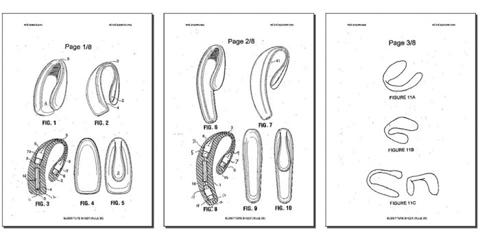
Recently the EAN magazine interviewed Frank Ferrari from we-vibe. The US company was granted the patent EP1824440. They applied in 2005. It took so long “at least in part to the filing of several third-party observations”. The patent is for a couple vibrator with a specific form. A couple vibrator is defined as a sex toy which permits sexual intercourse while inserted into the vagina.
Is this a patent which will destroy open-source sex toys in generel as it happened to Comingle? I don’t think so. You can still make a vibrator and sell it as long as it doesn’t have the form and functionality.
But: If you are interested in building couple vibrators (like we-vibe define them) then you have a problem. I don’t think the patent forbids every sex toy which can be inserted into the vagina while having sexual intercourse (sorry, but what is new about this??).
But if you design a similar form, equip it with vibrators then you definitely should consult your patent lawyer before selling it.
What is the unique about the form? Is it an innovation by we-vibe? Or is it rather a negative copy of a part of what we call genital area?
Or it is like giving a patent for T-shirts? A negative copy of the human upper body…
Maybe this is not a good example to blame patents. Maybe the EU patent agency has done a good job to grant a rather specific than general patent. Maybe we-vibe had enormous R&D efforts. Or they need enourmous effort to bring it into the market. And then a company makes a copy and sells it for the half of the price? Ok, then the we-vibe patent is ok.
My opinion: Patents are not good for innovation. They prevent innovations to become reality. They hinder competition. They support rich companies with large law departments. They promote lawyers and the economy of patents.
New small fusion vibrator
 This is a small version of the fusion vibrator. The small fusion form for molding can be made with 3d printers with smaller volume. In addition the inlay for the body interaction development board is reduced in size, but there is still enough place for board and battery. Only about 120ml silicone are needed. The form was constructed in Tinkercad.
Modify the form in Tinkercad: all forms, inlay only, form only
Download the STL files for printing: round_something_06_final_inlay_improved. There are some artifacts but printing is fine on the daVinci 1.0.
Download and discuss in Thingiverse: http://www.thingiverse.com/thing:1589075

Please follow the instruction from the large fusion vibrator. When you poor the silicone into the form it is very important to keep the USB connector free from silicone. Even very small amounts can cause the USB connector to break apart from the board. When the USB connector is broken then you cannot recharge the vibrator. Also be always very cautious when you plug-in or plug-out the USB connector.


Finally you can remove the overhanging parts from the inlay.


New vibrator design “fusion”
 bodyinteraction designed a lot of vibrating toys, some are usable as massage devices, some are explicit sex toys (vibrator ring, balls), some are experimental (collar). Everyone is motion controlled. If you have more than one they will influence each other remotely, eg. a vibrator and a vibrator ring.

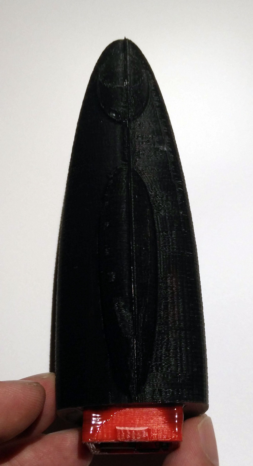
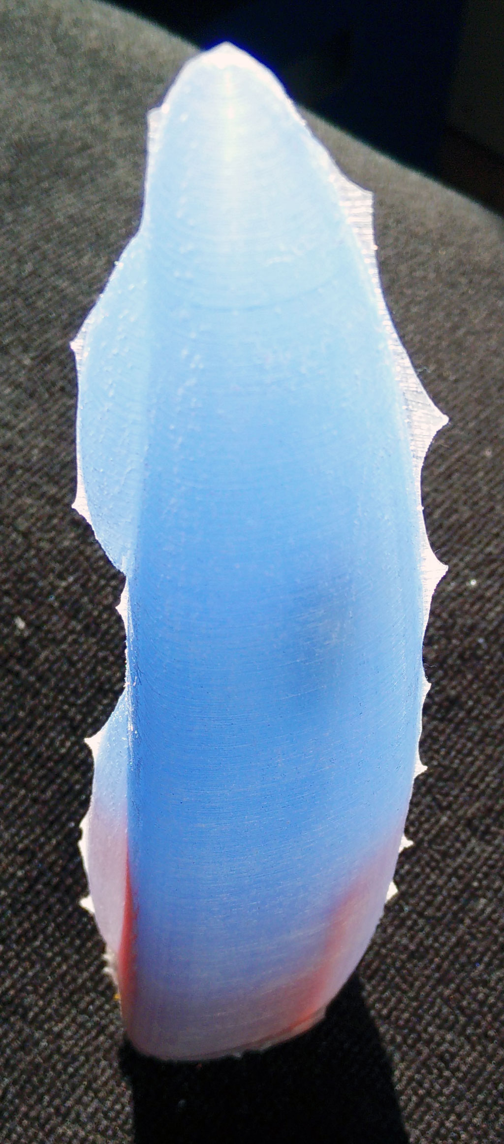
But a device like a classic big vibrator is still missing. So we designed the “fusion” which is approx 19cm long and up to 4+cm in diameter. It is called fusion as the case is made of silicone and 3d printed material (ABS).

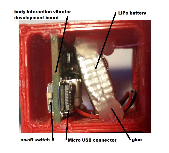
We have put the body interaction vibrator development board, motor and battery in a silicone form. There is an on/off switch – so when you travel the vibrator doesn’t wake up when it is moved. And you can charge the battery with a USB micro connector. There is a spacious inlay for the electronics, so it will be easy to get it done.
Pros:
- easy to charge the battery via USB
- on/off switch
- hard handle
- flexible upper part
- large (if you like this)
- ISP interface (“hacker port”) accessible
Cons:
- only the silicone part of the form can be put under water for cleaning
What do you need?
- 200 ml silicone with high shore A rate, eg. shore A 45 from silikonfabrik.de
- optional: special colour for silicone molding
- 3d print of the molding form, inlay and closure
- tinker wire
- body interaction vibrator development board with LiPo and motor (or similar Arduino boards)
- bin for preparing the silicone, something to stir the silicone
How much is it?
- Board, battery, motor: 30$ (buy at Tindie)
- Silicone: 10$
- 3d Prints: less than 5$
Step by step instructions
Step 1: Print out the inlay, the form and the enclosure
Download as zip-file: Fusion
Download at Thingiverse: http://www.thingiverse.com/thing:1505539
Step 2: Prepare the inlay: Insert the body interaction board and the LiPo battery
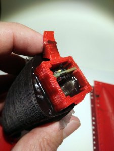
The body interaction vibrator development board is inserted into the provided rails. It it doesn’t fit in use a file to remove printing artefacts. Use some glue to fix the board. Then insert the battery and fix it.
Important: The Micro USB connector must be above the upper part of the inlay.
Step 3: fix the wires of the vibration motor
The vibration motor will hang down from the inlay as the inlay will be put in the form upside down. You can influence the position of the motor by shortening the wire or fixing the wire to e.g. to the battery. In this case the wire of the motor was threaded between battery and board. Therefore the motor will be in the middle of the vibrator.

 in the center there is the overmolded vibration motor
Step 5: Prepare the form
Use some tinker wire to “press” both parts of the form tight together. Use some wax to fix little holes in the form where the printer failed. (These are the white spots)

Step 6: Insert inlay into the form
There must be some space between inlay and form for the silicone.
Remark: The two wedge like forms at both sides of the inlay help to hold the inlay. The wedge can be removed after molding.
Step 7: Cast the silicone
Prepare the silicone as the producer recommends. It takes some time to pour the large amount of silicone into the narrow form. The silicone we use must be used within 10 minutes. So start at once after preparing the silicone.
Important: The USB micro connector, the switch and the ISP connector shouldn’t be dashed with silicone. If this happens remove the silicone. Maybe some silicone will remain behind. This can be removed later when the silicone is solid.
The battery is covered with silicone, the USB connecor and switch are not.
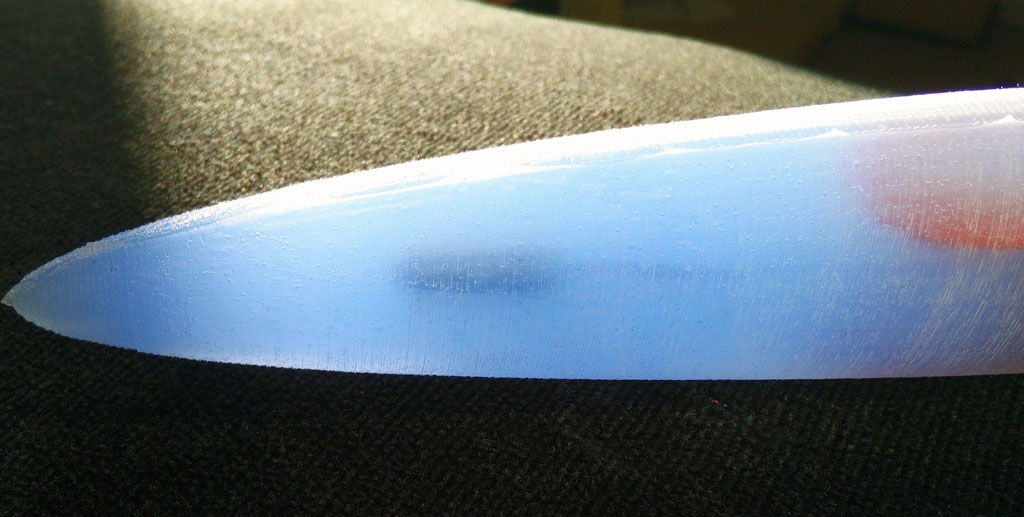
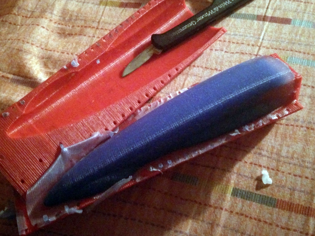
Step 8: Remove the form
Remove the tinker wire. Remove overhanging part of the silicone. Carefully tear both parts of the form away. You can use a knife, but be careful not to “hurt” the vibrator. Remove overhanging silicone at the vibrator. Also remove the two wedge like forms at both sides of the inlay.
Step 9: Install the closure
Now you can put the closure on the inlay. Fix the closure with glue. (Be careful! The USB connector is not very strong.) 


Tinker, share and download from Tinkercad:
form and inlay: https://tinkercad.com/things/b8nQxRn4XWl
closure: https://tinkercad.com/things/dhgtgeaYG0B
Download as zip-file: Fusion
Download at Thingiverse:
http://www.thingiverse.com/thing:1505539
New fusion 3d printed and silicone molded vibrator
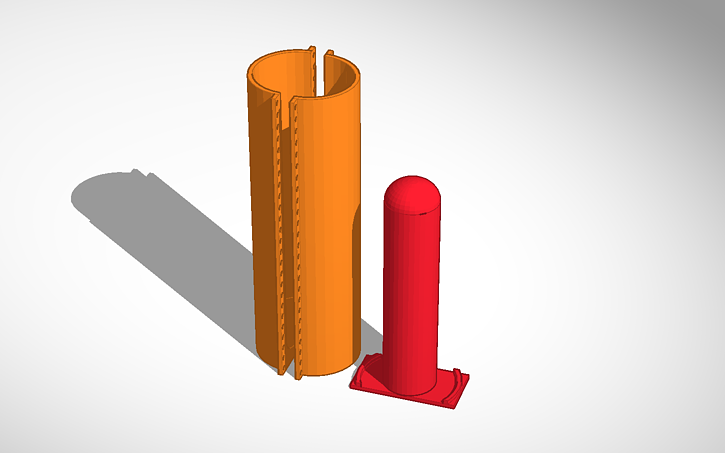
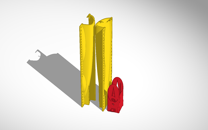
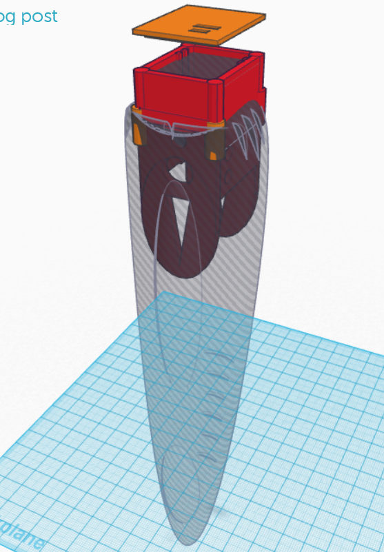 This is the initial design. The round curved form will be in silicone with vibration motor within (vibration motor not shown on sketch). The red part is 3d printed. It is the enclosure for the body interaction vibrator development board and LiPo battery. You can plug-in the Micro USB connector for battery charging. In addition there is an on/off switch e.g. for travelling.
Update for “balls revisted” – silicone molded vibrator
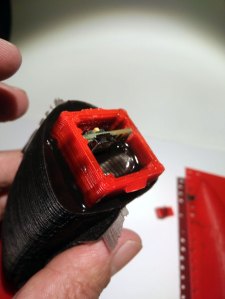
 The “ball revisited” silicone molded vibrator uses a wireless charging module. Unfortunately there are different version available. The version with some textile like cable jackets have a different inner radius of the receiver coil.
 We have changed the mounting on top of the picture as this type of the receiver coil needs a little more space. In addition the encasement is a bit larger.
  There is enough space for the body intercation board (top), wireless charging board (right) and the LiPo battery (below).
 Finally the wire of the vibration motor is glued in the middle of the encasement.
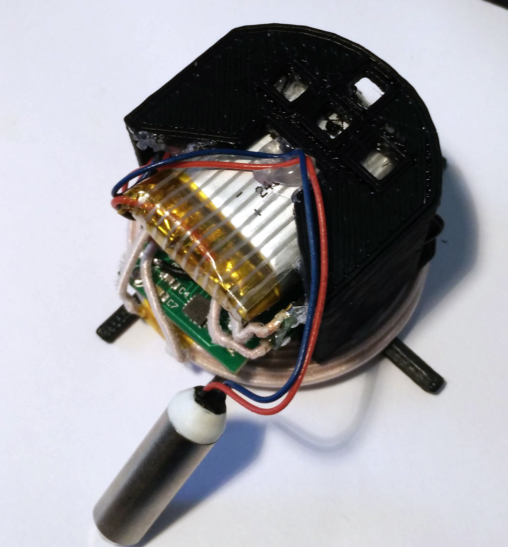 Please follow the “old” instruction – nothing has changed. When printing out the 3d parts use the new version 4 of the inlay. All 3d printing STL files at Thingiverse
