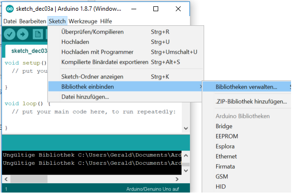
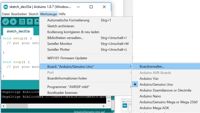
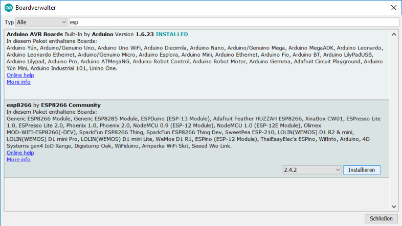
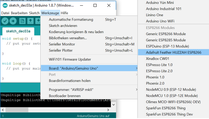
This in an intro to using and programming the BI2 with the Blnyk app. Read here how to set up Arduino. For a more general basic intro (based on the body interaction 1 board) read here.
Pins
 The communication between app and BI2 microcontroller is realized by pins. The idea is very easy: Each widget in the Blynk app is connected to a physical pin of the microcontroller. Every microcontroller has several pins where you can connect other electronic parts like a LED or a vibration motor. For each pin you have to configure if it is a output or input pin. Output pins are for controlling actuators, like LED, motor or display. Input pins are connected to sensors, like buttons, temperature sensors, acceleration sensor. In addition each pin can be digital, analog or virtual.
Digital output pins can only set the actuator to on or off e.g. turning the LED on or off. Analog pins can set the actuator to a specific value in a given range. Usual this in done in the range [0..255] or [0..1023]. For a motor 0 will set the motor off, 50 may be make the motor move very slowly and 255 will be full speed. An analog output pin is sometimes called PWM. (PWM is a method to simulate an analog signal with a sequence of digital on/off signals.)
Digital input pins can read the position of a button (on/off). Analog input pins can read a value in a given range, e.g. the acceleration in the X-axis or the temperature.
So what you have to do to connect a widget to a pin? Just set the widget (e.g. on/off switch widget) to the pin you want to set on/off (e.g. a pin which is connected to a LED). That’s all. No programming required. All you need is this small program which must be uploaded to the microcontroller with the Arduino IDE.
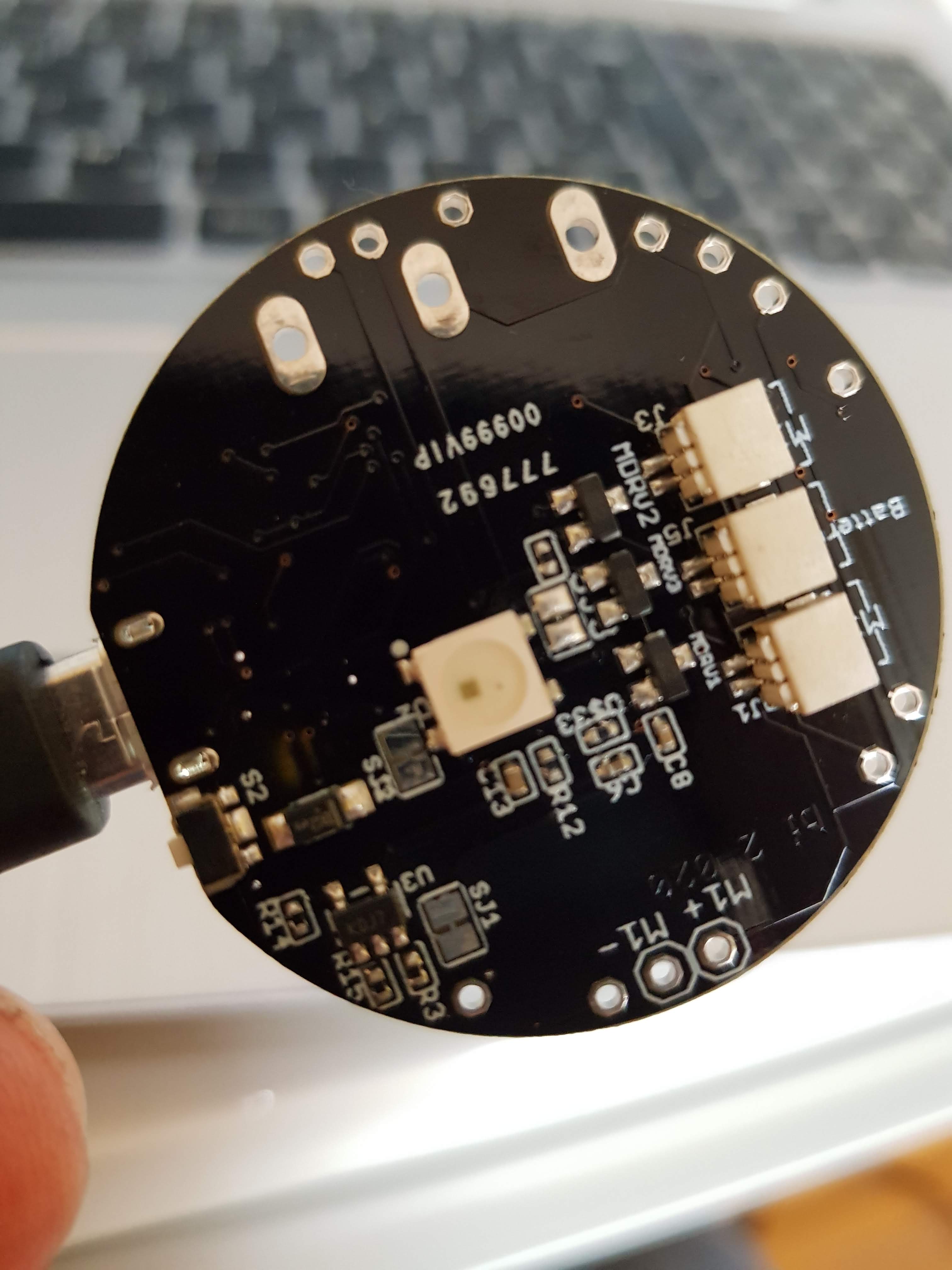
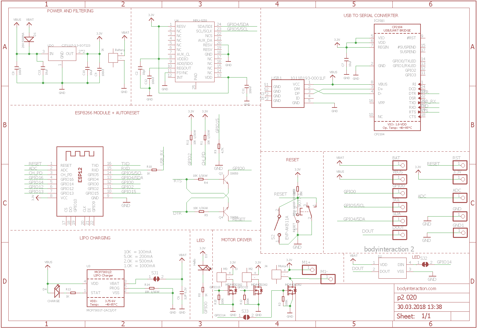
The body interaction 2 use the ESP8266 microcontroller. There are 16 pins, all could be used as digital or analog, input or output. But only pin 12 and 13 are free to use (the rest if for internal communication). Pin 14 is connected to the LED WS2821B.
The Arduino sketch
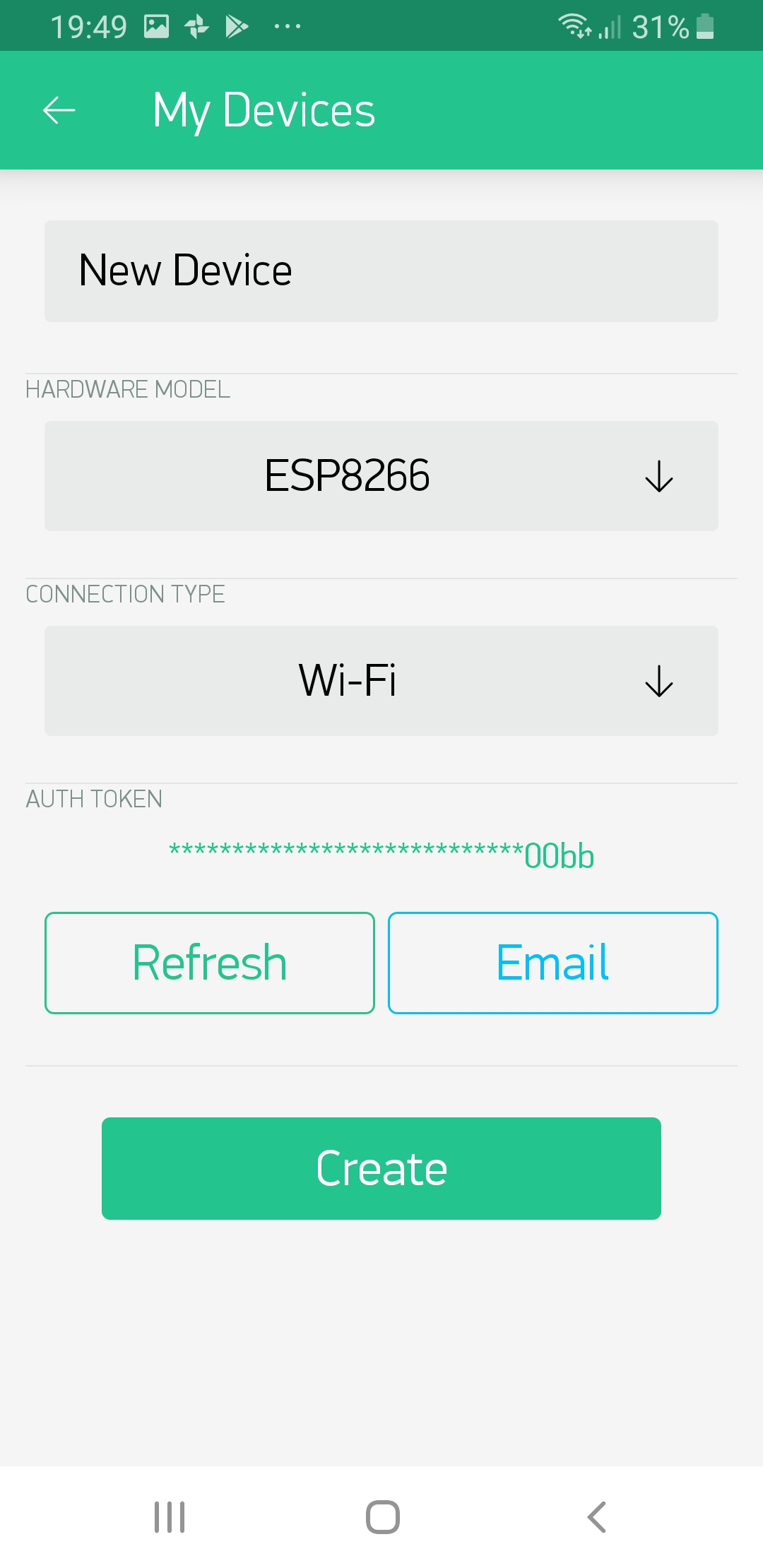
The first 3 lines are for configuring Blynk and using two libraries. The 3 variables auth, ssid and pass are defined. (The variables are from thy type char (=character) and in this case it is not only one character but an array which you can see by the “[” and “]”. Here you have to add your AUTH token from the Blynk app, and SSID and password from your local WLAN/WIFI.
#define BLYNK_PRINT Serial
#include <ESP8266WiFi.h>
#include <BlynkSimpleEsp8266.h>

char auth[] = "XXXXXXXXXXXXXXXXXXXXXXXXXXX";
char ssid[] = "XXXXXXXX";
char pass[] = "XXXXXXXX";
Each Arduino program consists of a setup and a loop procedure. The setup is called only one time when the microcontroller is started (or connected to a battery). It is used to initialize the microcontroller, in this case Blynk is started. The loop will be called indefinitely and all statements are executed in the given order. To get Blynk running you have to call Blynk again and again (“Blynk.run();”). According to the Blynk manual, you should not add a delay() function here, because this could disturb the communication between the app and the microcontroller.
void setup() {
  Blynk.begin(auth, ssid, pass);
}

void loop() {
  Blynk.run();
}
Virtual pins
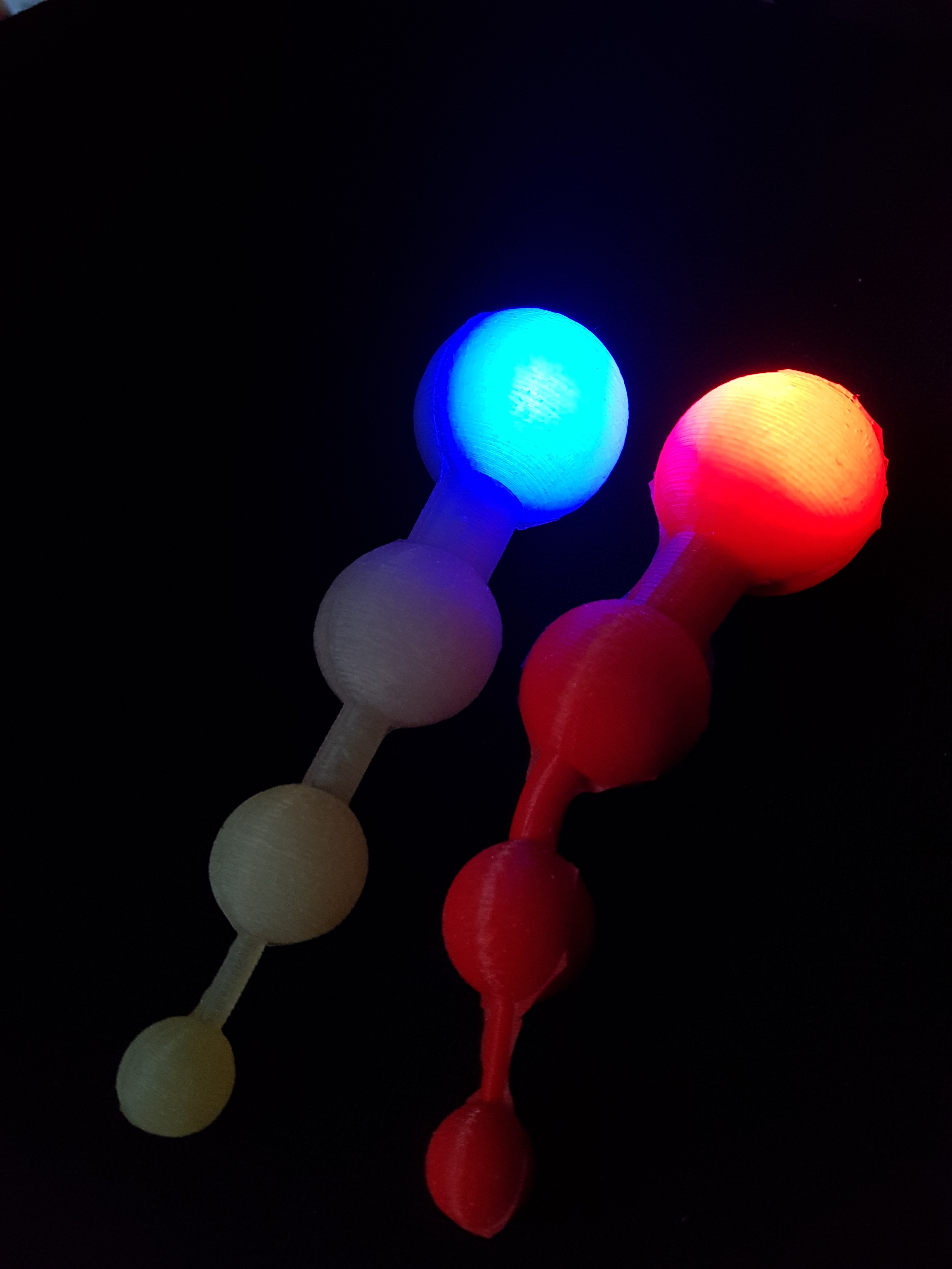
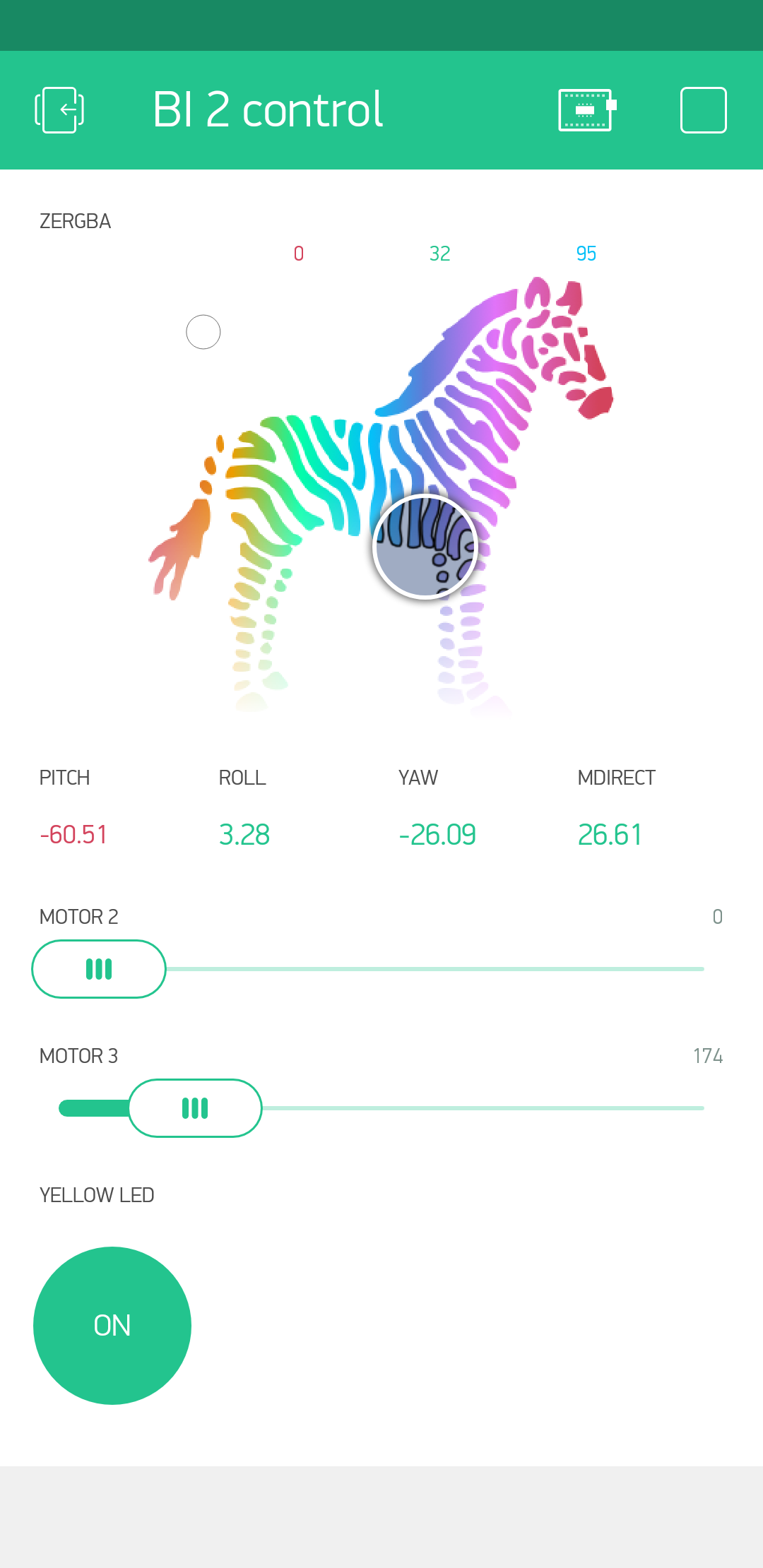
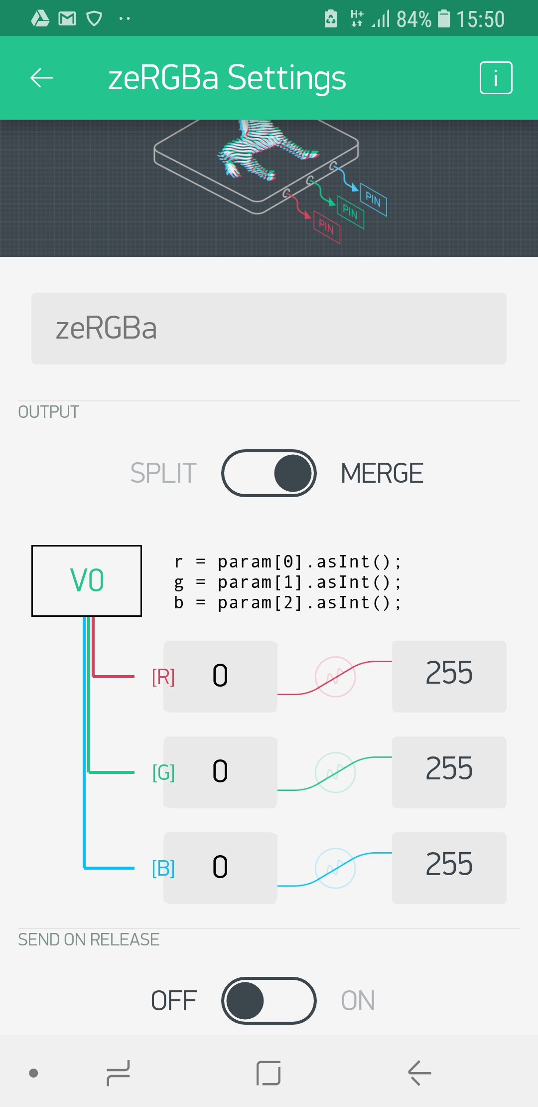
 So far communication is only possible with physical pins. But how can you exchange other information? Maybe you want to tell the microcontroller to “shut up immediately”, or you want to play a given vibration pattern like a sinus curve. For this you can use “virtual pins”. (IMHO there is no reason to call this mean of data exchange “virtual” and it is has nothing to do with a pin. You can call it a variable or channel for data exchange.) The zeRGBa widget is a good example. The color of the LED is controlled by 3 values, the amount of red, green and blue color. This 3 values can be connected to one virtual pin (“V0”) and then they will be transmitted to the microcontroller. To change the color of the LED you have to program the microcontroller to read out the amount of each color and set the LED to the appropriate value.
We will demonstrate virtual pins with the LED. The WS2821B LED is connected to pin 14, but you cannot control the LED directly by setting the pin to a given value. This is done by a library which controls the LED.
First we have to include the library, we use FastLED.
#include "FastLED.h"
Then we have to tell how many LEDs we have (you can put several of them in a chain). The BI2 has only one on board (but you can add more).
#define NUM_LEDS 1 // number of LEDs
The you have to tell to which physical pin the LED is connected (14). Finally you have to set up a (instance of an) object “CRGB” for the LED where all relevant data is hidden.
#define DATA_PIN 14 // pin for LED
CRGB leds[NUM_LEDS]; // define the array of leds
Now comes the more difficult part. The zeRGBa widget has 3 values (one for red, one for green, one for blue) and all are put in the virtual variable V0.
We have add a new function called “BLYNK_WRITE(V0)”. To get the first value we have to read out “param[0]”, for the second “param[1]” etc. We want to store this first value in a variable “i” of the type integer. To assure that param[0] is also from the type integer we add “.asInt()”. The value for red is put in variable i, green in j and blue in k.
BLYNK_WRITE(V0) {
  int i = param[0].asInt();
  int j = param[1].asInt();
  int k = param[2].asInt();
}
Now we have to tell the function BLYNK_WRITE what to do with the values i, j an k. This is done by using the method setRGB which is attached to the LED (which is number 0)
leds[0].setRGB(j,i,k);
Now we can make changes to other LEDs (if we have more than one). If you are ready you have to tell the LED to show the new color.
FastLED.show();
In addition a new statement has to be added to setup the LED within the setup part.
void setup() {
  FastLED.addLeds<WS2812B, DATA_PIN, RGB>(leds, NUM_LEDS);
  [...]
Now we can put everything together the script will look like this:
/*************************************************************
Controling the body interaction 2 board with the Blynk app
*/

#define BLYNK_PRINT Serial
#include <ESP8266WiFi.h>
#include <BlynkSimpleEsp8266.h>

// Auth Token infor the Blynk App.
char auth[] = "XXXXXXXXXXXXXXXXXXXXXXXXXXX";

// Your WiFi credentials.
char ssid[] = "XXXXXXXX";
char pass[] = "XXXXXXXX";

// Library for controlling the WS2821B (Neopixel) LED or LED strip
#include "FastLED.h"
#define NUM_LEDS 1 // number of LEDs
#define DATA_PIN 14 // pin for LED
CRGB leds[NUM_LEDS]; // define the array of leds

// This function set the LED color according to the selected RGB values in the app.
// RGB values are controlled in the app with zeRGBa widget
// values are stored in the virtual pin V0
// V0 consists of 3 values for Red, Green, Blue
BLYNK_WRITE(V0) // set LED RGB color values
{
  int i = param[0].asInt();
  int j = param[1].asInt();
  int k = param[2].asInt();
  leds[0].setRGB(j,i,k);
  FastLED.show();
}

void setup()
{
  // init LEDs
  FastLED.addLeds<WS2812B, DATA_PIN, RGB>(leds, NUM_LEDS);

  // connect to Blynk
  Blynk.begin(auth, ssid, pass);
}

void loop()
{
  Blynk.run();
}
Do you like this, do you need this, do you understand this? Tell me jacardano@gmail.com