
Maybe you want to add some vibration pattern to your BI2 toy? With the Blynk app you can easily add a slider to control the speed of the vibration motor. But how do you implement a sinus mode? First, you have to introduce a way to remember that you are in this sinus mode. this is easily done by introducing…
Category: vibrator
The new BI2 black vibrator development board
The new black BI2 board is ready. I have a few assembled boards ready for shipping. Have a look at www.tindie.com
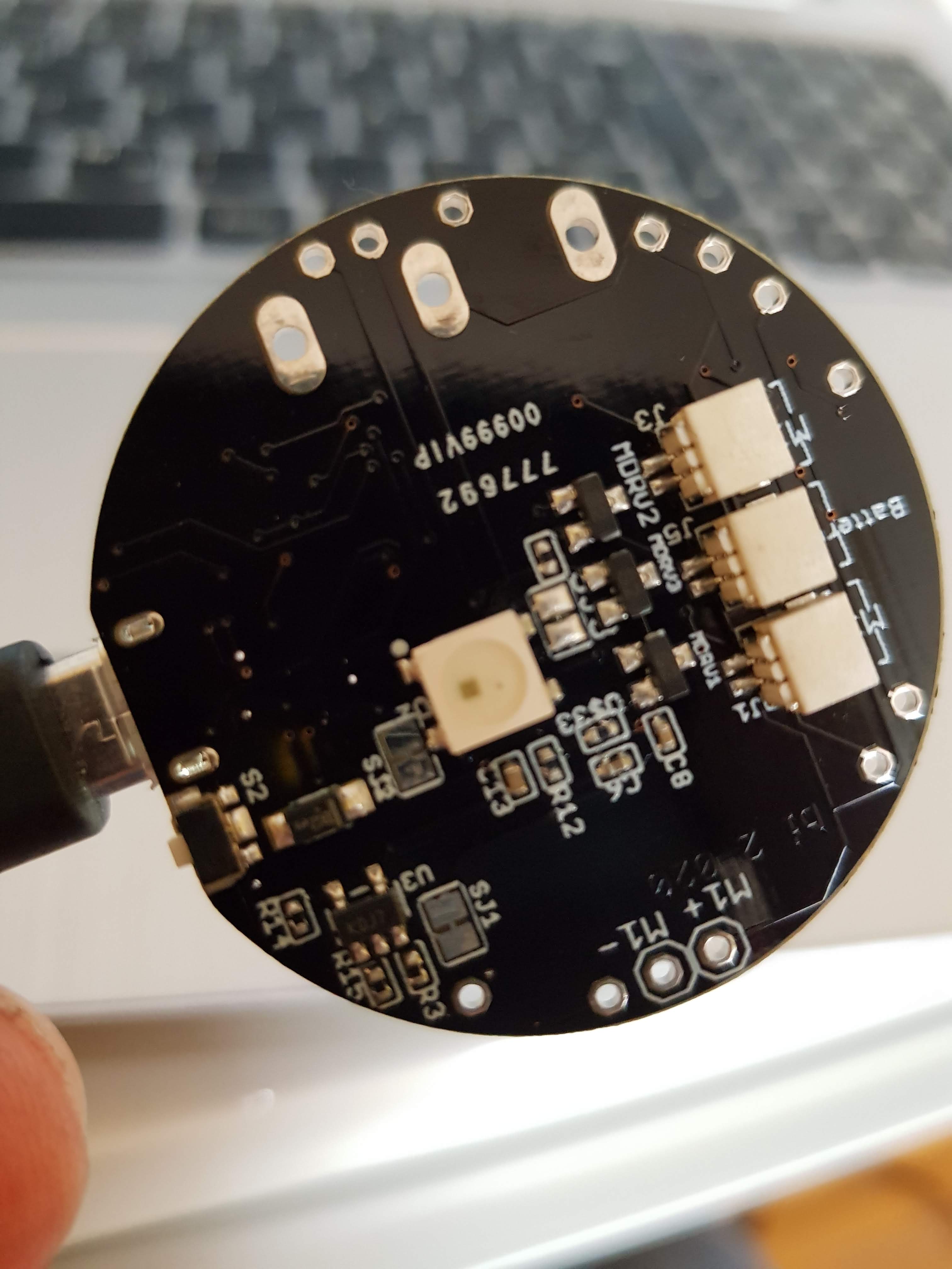
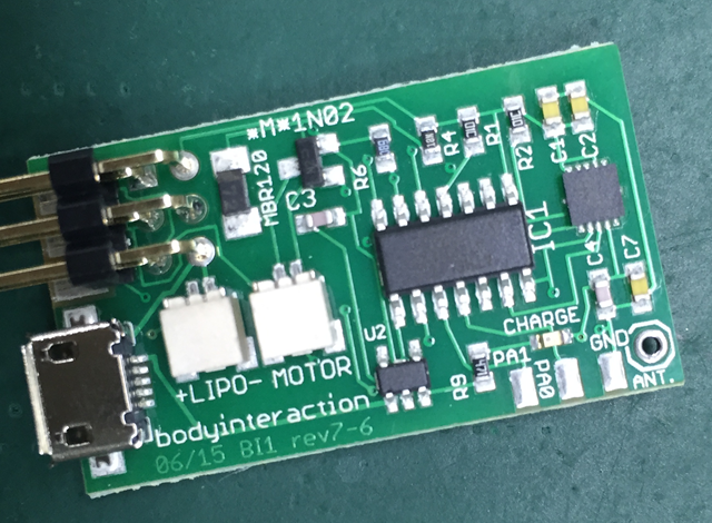
3 JST 1mm plugs (battery, motor 2, motor 3), LED, reset button, M+/M- is for motor 1

JST 1mm plug for motor 1, alternative RESET button
Features
- ESP8266 Microcontroller with WLAN
- MPU9250 (accelerometer, gyroscope)
- LiPo battery charging
- 3 motors can be connected (simple motor driver circuits)
- 1 WS2812B LED – a colourful LED (16 Mill. colours). They are commonly known as Adafruit Neopixel – a strip or a ring of individual programmable LEDs (when use the WS2812B only two motors can be connected)
- design based on the great Adafruit Feather Huzaah ESP8266
- vibration motors and LiPo battery can be easily connected with JST 1mm connectors
- two reset buttons (the button next to the USB connector can be overmolded)
- USB connector for battery charging and code uploading
- programmable with the Arduino IDE or NodeMCU
- white LED for indicating charging
- standard LED (yellow) on GPIO00
- round 40mm diameter

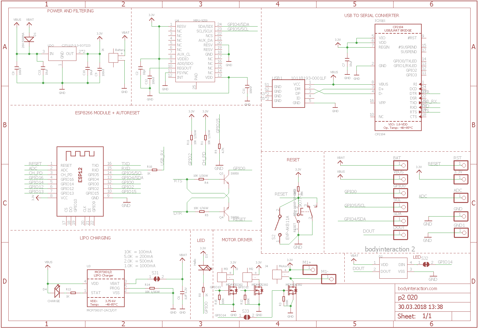
There are 3 free GPIO ports. Standard layout are for driving 2 motors (GPIO 12 = M2, GPIO 13 = M3) and 1 LED (GPIO14). Alternatively you can use 3 motors (GPIO12,13,14) but no LED.
Standard: SJ2 not connected, SJ3 connected
Alternative: SJ2 connected, SJ3 not connected
Here is the schematic which is adapted from Adafruit.
References:

Sex toy patents arrived in the EU
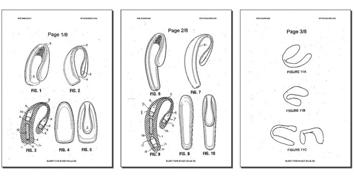
Recently the EAN magazine interviewed Frank Ferrari from we-vibe. The US company was granted the patent EP1824440. They applied in 2005. It took so long “at least in part to the filing of several third-party observations”. The patent is for a couple vibrator with a specific form. A couple vibrator is defined as a sex toy which permits sexual intercourse while inserted into the vagina.
Is this a patent which will destroy open-source sex toys in generel as it happened to Comingle? I don’t think so. You can still make a vibrator and sell it as long as it doesn’t have the form and functionality.
But: If you are interested in building couple vibrators (like we-vibe define them) then you have a problem. I don’t think the patent forbids every sex toy which can be inserted into the vagina while having sexual intercourse (sorry, but what is new about this??).
But if you design a similar form, equip it with vibrators then you definitely should consult your patent lawyer before selling it.
What is the unique about the form? Is it an innovation by we-vibe? Or is it rather a negative copy of a part of what we call genital area?
Or it is like giving a patent for T-shirts? A negative copy of the human upper body…
Maybe this is not a good example to blame patents. Maybe the EU patent agency has done a good job to grant a rather specific than general patent. Maybe we-vibe had enormous R&D efforts. Or they need enourmous effort to bring it into the market. And then a company makes a copy and sells it for the half of the price? Ok, then the we-vibe patent is ok.
My opinion: Patents are not good for innovation. They prevent innovations to become reality. They hinder competition. They support rich companies with large law departments. They promote lawyers and the economy of patents.
New small fusion vibrator
 This is a small version of the fusion vibrator. The small fusion form for molding can be made with 3d printers with smaller volume. In addition the inlay for the body interaction development board is reduced in size, but there is still enough place for board and battery. Only about 120ml silicone are needed. The form was constructed in Tinkercad.
Modify the form in Tinkercad: all forms, inlay only, form only
Download the STL files for printing: round_something_06_final_inlay_improved. There are some artifacts but printing is fine on the daVinci 1.0.
Download and discuss in Thingiverse: http://www.thingiverse.com/thing:1589075

Please follow the instruction from the large fusion vibrator. When you poor the silicone into the form it is very important to keep the USB connector free from silicone. Even very small amounts can cause the USB connector to break apart from the board. When the USB connector is broken then you cannot recharge the vibrator. Also be always very cautious when you plug-in or plug-out the USB connector.


Finally you can remove the overhanging parts from the inlay.


New vibrator design “fusion”
 bodyinteraction designed a lot of vibrating toys, some are usable as massage devices, some are explicit sex toys (vibrator ring, balls), some are experimental (collar). Everyone is motion controlled. If you have more than one they will influence each other remotely, eg. a vibrator and a vibrator ring.

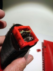
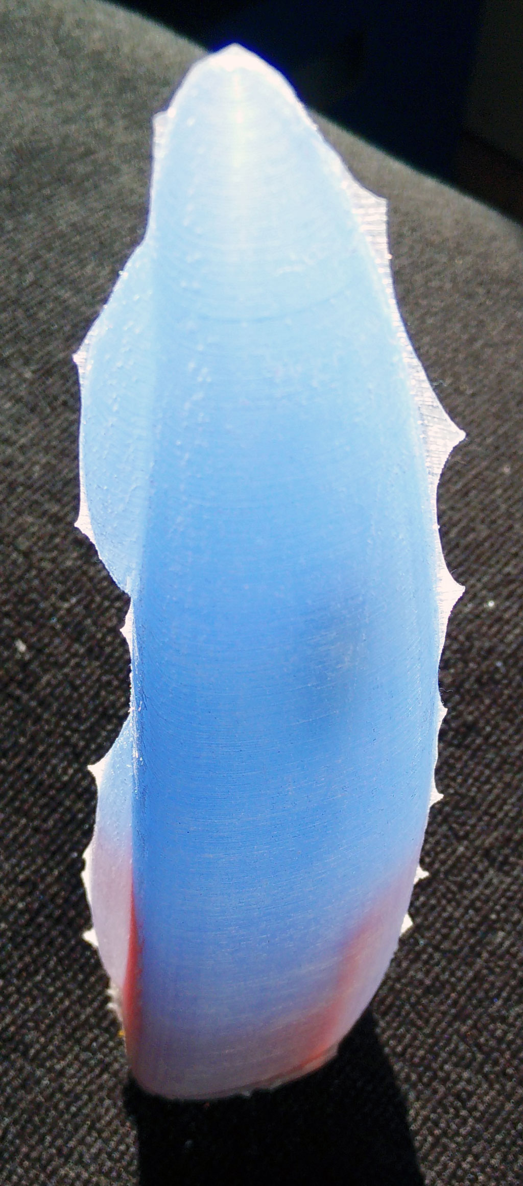
But a device like a classic big vibrator is still missing. So we designed the “fusion” which is approx 19cm long and up to 4+cm in diameter. It is called fusion as the case is made of silicone and 3d printed material (ABS).

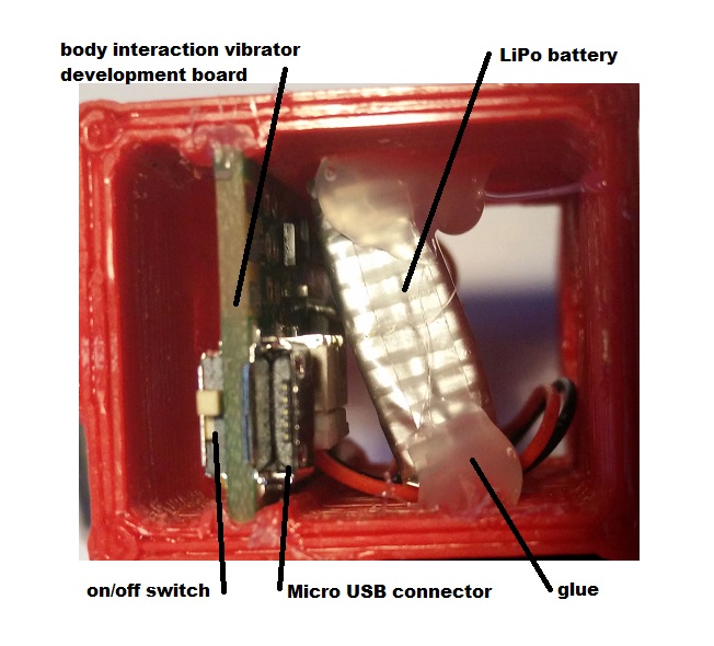
We have put the body interaction vibrator development board, motor and battery in a silicone form. There is an on/off switch – so when you travel the vibrator doesn’t wake up when it is moved. And you can charge the battery with a USB micro connector. There is a spacious inlay for the electronics, so it will be easy to get it done.
Pros:
- easy to charge the battery via USB
- on/off switch
- hard handle
- flexible upper part
- large (if you like this)
- ISP interface (“hacker port”) accessible
Cons:
- only the silicone part of the form can be put under water for cleaning
What do you need?
- 200 ml silicone with high shore A rate, eg. shore A 45 from silikonfabrik.de
- optional: special colour for silicone molding
- 3d print of the molding form, inlay and closure
- tinker wire
- body interaction vibrator development board with LiPo and motor (or similar Arduino boards)
- bin for preparing the silicone, something to stir the silicone
How much is it?
- Board, battery, motor: 30$ (buy at Tindie)
- Silicone: 10$
- 3d Prints: less than 5$
Step by step instructions
Step 1: Print out the inlay, the form and the enclosure
Download as zip-file: Fusion
Download at Thingiverse: http://www.thingiverse.com/thing:1505539
Step 2: Prepare the inlay: Insert the body interaction board and the LiPo battery
The body interaction vibrator development board is inserted into the provided rails. It it doesn’t fit in use a file to remove printing artefacts. Use some glue to fix the board. Then insert the battery and fix it.
Important: The Micro USB connector must be above the upper part of the inlay.
Step 3: fix the wires of the vibration motor
The vibration motor will hang down from the inlay as the inlay will be put in the form upside down. You can influence the position of the motor by shortening the wire or fixing the wire to e.g. to the battery. In this case the wire of the motor was threaded between battery and board. Therefore the motor will be in the middle of the vibrator.

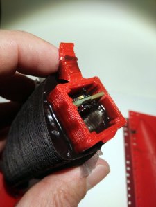
 in the center there is the overmolded vibration motor
Step 5: Prepare the form
Use some tinker wire to “press” both parts of the form tight together. Use some wax to fix little holes in the form where the printer failed. (These are the white spots)

Step 6: Insert inlay into the form
There must be some space between inlay and form for the silicone.
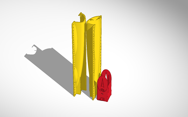
Remark: The two wedge like forms at both sides of the inlay help to hold the inlay. The wedge can be removed after molding.
Step 7: Cast the silicone
Prepare the silicone as the producer recommends. It takes some time to pour the large amount of silicone into the narrow form. The silicone we use must be used within 10 minutes. So start at once after preparing the silicone.
Important: The USB micro connector, the switch and the ISP connector shouldn’t be dashed with silicone. If this happens remove the silicone. Maybe some silicone will remain behind. This can be removed later when the silicone is solid.
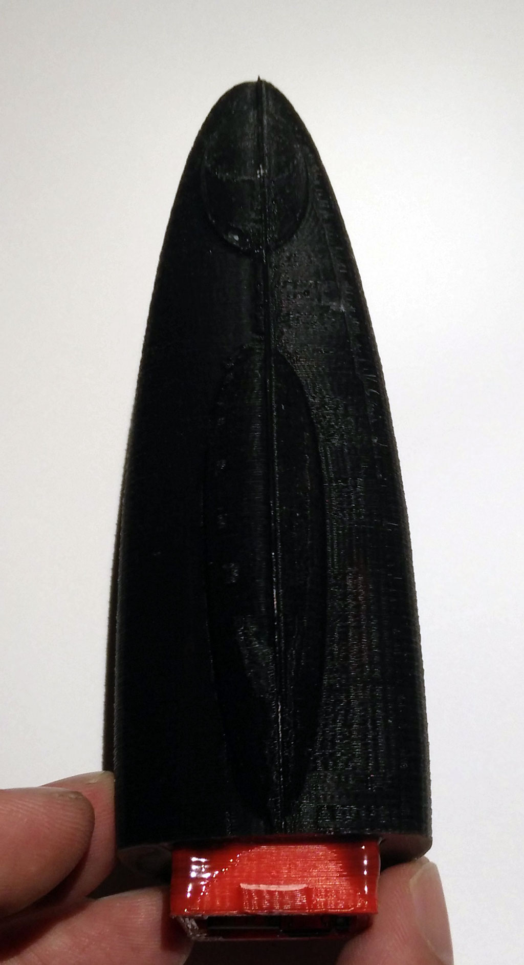
The battery is covered with silicone, the USB connecor and switch are not.
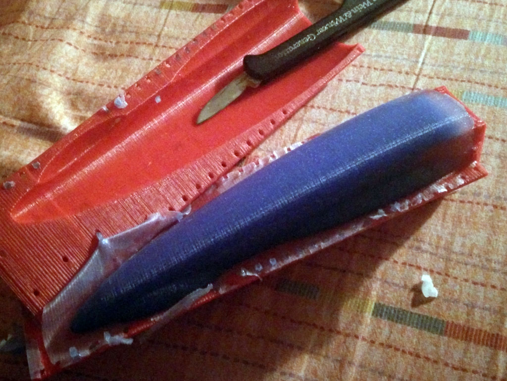
Step 8: Remove the form
Remove the tinker wire. Remove overhanging part of the silicone. Carefully tear both parts of the form away. You can use a knife, but be careful not to “hurt” the vibrator. Remove overhanging silicone at the vibrator. Also remove the two wedge like forms at both sides of the inlay.
Step 9: Install the closure
Now you can put the closure on the inlay. Fix the closure with glue. (Be careful! The USB connector is not very strong.) 


Tinker, share and download from Tinkercad:
form and inlay: https://tinkercad.com/things/b8nQxRn4XWl
closure: https://tinkercad.com/things/dhgtgeaYG0B
Download as zip-file: Fusion
Download at Thingiverse:
http://www.thingiverse.com/thing:1505539
Update for “balls revisted” – silicone molded vibrator
 The “ball revisited” silicone molded vibrator uses a wireless charging module. Unfortunately there are different version available. The version with some textile like cable jackets have a different inner radius of the receiver coil.
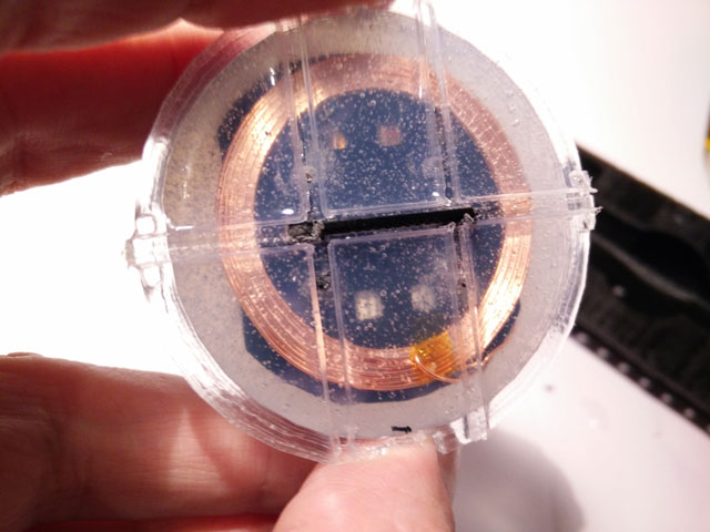
 We have changed the mounting on top of the picture as this type of the receiver coil needs a little more space. In addition the encasement is a bit larger.
  There is enough space for the body intercation board (top), wireless charging board (right) and the LiPo battery (below).
 Finally the wire of the vibration motor is glued in the middle of the encasement.
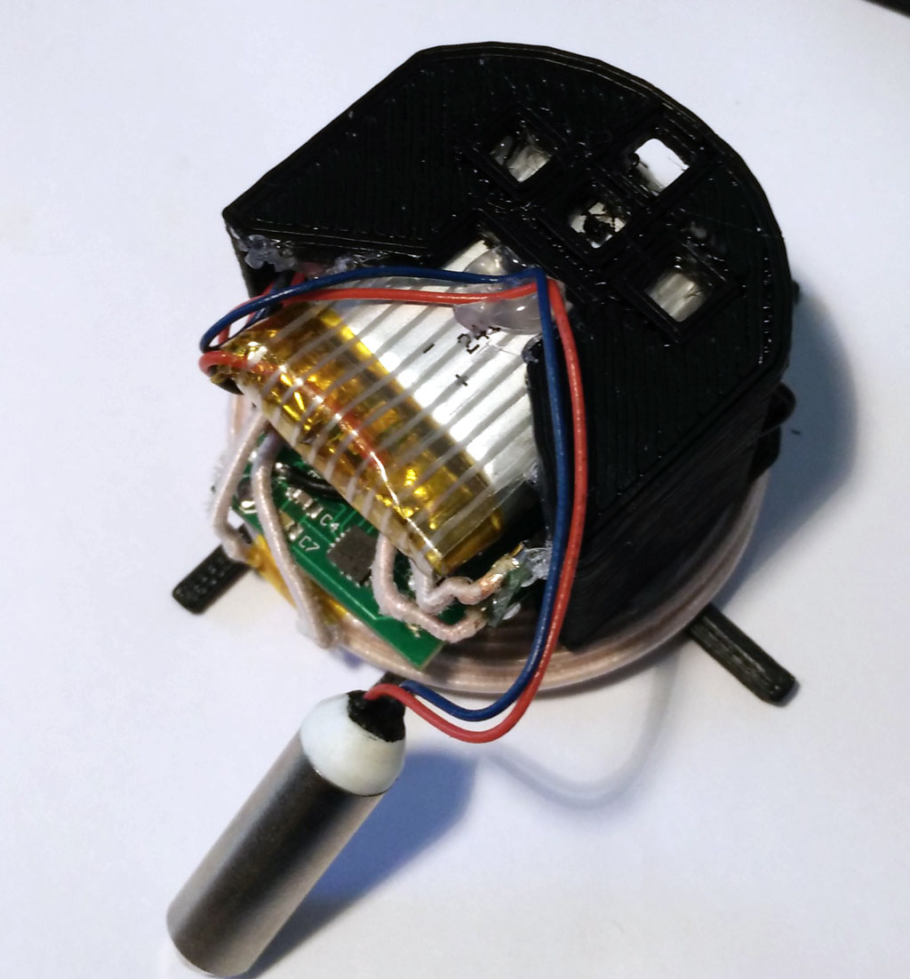 Please follow the “old” instruction – nothing has changed. When printing out the 3d parts use the new version 4 of the inlay. All 3d printing STL files at Thingiverse
Silicone overmolded vibrator – balls revisited
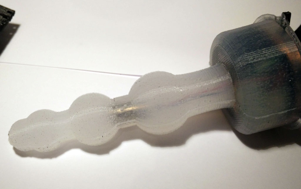
 Building your own silicone molded vibrator becomes now easier. We already have presented 3d printed forms for building your personal vibrator (massage wand, wireless charged vibrator). The vibrator uses the body interaction vibrator development board. The body interaction board has a Arduino compatible microcontroller, vibration strength control by motion, a vibration motor and a rechargeable battery.
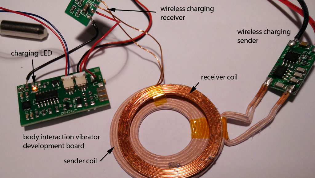
 What is new? The electronics including battery are in the base of the vibrator. We developed a 3d printed enclosure for the electronics. This has several benefits: The assembling of the electronics and the molding itself is easier as everything is fixed within the enclosure. And it is more safe as the enclosure shields the electronics from the environment (and vice versa). In addition we used a different charging module from Seeed Studio. The input voltage is only 5V. Now you can connect the charging module with a USB connector and don’t need another power supply. (Look here for an explanation of wireless charging sender and receiver.)

Another improvement is the placing of the vibration motor. The vibration motor can now be placed in the center of the vibrator and it different heights. Just were you need the power.
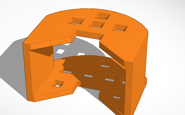
 Finally the mounting is improved. The mounting holds the enclosure when it is inserted into the form.
 The mounting (together with the enclosure with the electronics) is inserted into the form. The form consists of two parts which must be fastened together by tinker wire. It is a variation of the ball theme.
We present a step by step procedure for tinkering the vibrator. You need:
- 3d printed form (molding form, 2 parts)
- 3d printed enclosure
- 3d printed mounting
- body interaction vibrator development board
- silicone with a high shore A value (eg. shore A 45 which is quiet hard but still flexible), approx. 100 ml
- wireless charging module eg. from Seeed studio
- soldering station, (hot) glue
Step by step procedure:
A. Print out all forms. You can download the forms from Thingiverse.
B. Connect the wireless charging module to the body interaction vibrator development board.
B.1 You have to solder a wire connecting (-) on the wireless charging module and GND on the body interaction board.
B.2 Now comes the tricky part. You have to connect (+) from the charging module with the body interaction board. Solder a wire at (+) of the charging module. But where do you solder the wire on the body interaction board? Unfortunately the wireless charging option was not taken into consideration during the development of the board. So there is no appropriate connection on the board.
 The best solution is to unsolder the USB connector and connect to + of the USB connection. The easiest way to unsolder the surface mounted USB connector is done with a hot air soldering station. Alternatively you can solder the wire directly to the MAX1555 module – this solution is presented here. In any case: Be careful not to break the tiny pads connecting pcb and USB connector.
B.3 Connect the sender module with a 5V power supply. You can use a USB cable, dismantle the cable and connect the black and red wires.

C. Place the receiver charging coil on top of the enclosure. The diameter of the top side is a bit larger than the diameter of the bottom side. Use some glue to fix the coil. Don’t fix the mounting now. It is easier to do it later (step E).
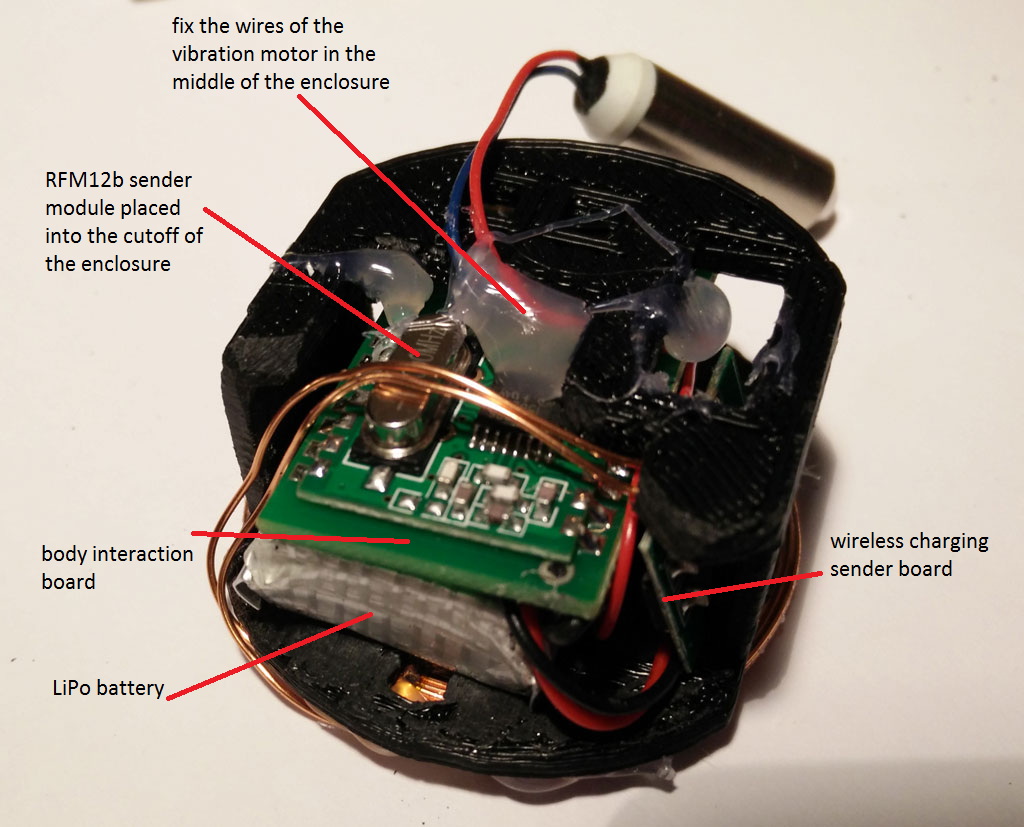
D. Put the electronics into the enclosure: Begin with the body interaction board. The RFM12b is quite large so place it at an outer position. Then insert carefully the LiPo battery. Don’t force it! The plugs for the battery and the motor could break. If you have done so insert the tiny wireless charging receiver board. At the end fix the wires of the vibration motor in the middle of the enclosure.
E. Connect the mounting with the enclosure. There are 2 holes provided where the mounting fits into the enclosure. Use some glue to stick together both parts. (see picture above step C).

F. Put together both parts of the molding form. Use tinkering wire to attach both parts tight together. Then insert the enclosure into the form. Check the wireless charging function. The yellow LED must be on when you place the charging coil over the receiver coil.

G. Now poor silicone into the molding. We use Shore A 45 silicone which is rather hard. The silicone has to dry for some hours or days. Read the instructions of your silicone provider.

H. When the silicone is hard, you can remove the tinkering wire. Then carefully remove the form.


I. Remove the overhang.
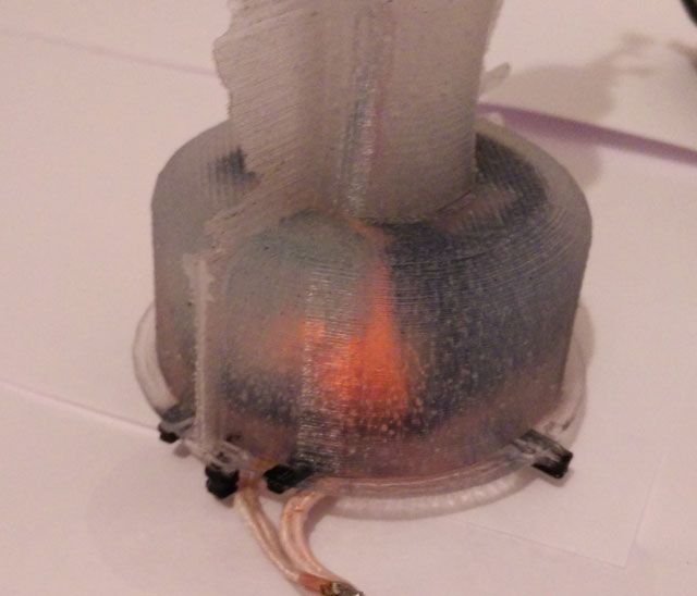
J. Test the wireless charging. The orange LED must be on when both coils are near together.

K. Remove the mounting.
Design your own forms using Tinkercad. Start now and share!
Old versions of the enclosure:Enclosure & mounting togther, Enclosure , Mounting
Download the STL files for 3d printing from Thingiverse.
Update 2016/03/12: Added image of circuits showing where to solder the wireless charging module.
Update 2016/04/05 redesign of mounting and enclosure due to different versions of the wireless charging receiver coil
Programming Tutorial part 4: Sinus

Nervous Optic by Ben Felten, CC BY-ND 2.0
In tutorial 3 – “ramps” we learned how to repeat instructions again and again using the for statement. In this tutorial we need the for loop again, bur instead of changing the motor speed by a constant value we want a more dynamic behavior. Therefore we use the sinus function – a classical pattern used for controlling vibrators.
Here is a straight forward approach:
for (float i = 0; i < 20000; i = i + 0.05) {
  analogWrite(motor, (sin(i)); //motor speed set to sin(i)
}
delay(20);
We are changing the variable i in small steps of 0.05. So the variable i will become 0, 0.05, 0.1, 0.15, 0,2 … and so on.
But this doesn’t work. Let’s have a look at the sinus function. Just use the google search and type in “sin(x)”. You will see the following curve:
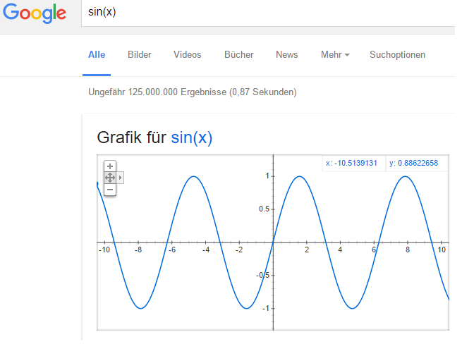
There are two problems:
- There are values below 0 (on the vertical or y-axis). If the value is 0 or below 0 the motor is off.
- The maximal value is 1. But we need values between the minimal motor speed (around 40) and the maximal speed (always 255).
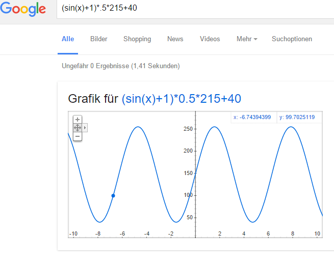
You can try to adjust the function and visualize it with google search. Maybe you will discover an interesting variant of the sinus curve.
We use the following function:
(sin(x)+1) 0.5 * (maximal motor speed – minimal motor speed)) + minimal motor speed
- Sin(x)+1: add 1 to get positive values only between 0 and 2 instead of -1 and 1.
- Multiply by 0.5: get values between 0 an 1 instead 0 and 2
- Multiply with maximal motor speed (255) – minimal motor speed (40): values are now between 0 and 215
- Add minimal speed: values are between 40 and 255. So the motor will always be on.
This is the script. Please have a look at tutorial 2 if you don’t know how to upload the script.
 // www.bodyinteraction.com tutorial sinus
int motor = 3;
int minimal_motorspeed = 50;

void setup() {
  pinMode(motor, OUTPUT);
}
void loop() {
  for (float i = 0; i < 20000; i = i + 0.05) {
    analogWrite(motor, ((sin(i) + 1) * 0.5 * 215) + 40);
    delay(5);
  }
}
If you want to slow down the changes in the motor speed change delay(5) and take larger values.
Go back to tutorial 3: ramps
Review of vibrator development boards
Designing your own sex toys with advanced technology is becoming popular. Although the community is still very small the interest is rising. In this article we will introduce for open source vibrator development boards including our body interaction 1. We will see how the design of the development boards determines the design space – the possibilities of sex toys which can be realized.
 Comingle may be the most successful open source sex toy company. They invented the Mod – an Arduino based vibrator with 3 vibration motors. They also offer the Dilduino – a development board based on the Atmel ATmega342U4 (similar to the Arduino Micro). The board can drive 3 vibration motors. They have developed a great library for programming vibration pattern (“OS sex“). You can use arbitrary function like sinus or cosinus to define pattern. You can upload programs via the USB connection, but there is no wireless radio or WiFi connection on board. The board lacks battery charging support, so you need external power. As the board is quite large it is only suitable for larger toys. Available at Tindie.
Pro: supports 3 motors, full Arduino compatible, great library, superb tutorials
Cons: no wireless connectivity, no battery charger, quite large for being part of a sex toy
 Pen 15 shield is a shield for the Arduino Uno. So you need an Arduino Uno in addition to the shield. The shield must be connected to the Arduino board. It has one driver for a vibration motor. This pioneer work was announced in 2011, but it is probably not available any more. The price is quite low. There is no battery charging option and it is very large compared to the other boards.
Pro: full Arduino compatible
Cons: no wireless connectivity, no battery charger, too large to be part of a sex toy
Master Beta Kit from Orgasmatronic Inc. is another shield for the Arduino Uno. It can control two vibration motors. The power source for the vibration motors could be different though you may control motors with different input voltages. Easy assembling and support with online tutorials.
Pro: full Arduino compatible, different motor input voltage
Cons: no wireless connectivity, no battery charger, too large to be part of a sex toy
 The body interaction development board can drive one motor. It has a LiPo battery charging option. It can be controlled by motion – a 3-axis accelerometer is build in. Using motion you can control the vibrator – no need for further peripherals like switches or slider for controlling the vibration speed. The main advantage is the wireless radio especially if you like to use more than one sex toy at once. You can transmit data between your toys, control your toys or even synchronize them. The form factor is very small, though it can be part of a small toy. As the board is only 20x36mm there is not much space for further functionalities: It has no serial interface. To upload a program you need an ISP programmer (eg USBtinyISP). And it uses a microcontroller from the ATMEL ATtiny series. Although the tiny microcontrollers are getting more and more popular they have some disadvantage compared to the standard ATmega328p: There is not much memory on the chip (8K instead 32K), some libraries may not work, less I/O ports. Available at Tindie.
Pro: small form factor, LiPo battery charger included, wireless radio, motion tracking
Cons: some libraries don’t work, programmer needed for uploading programs

From Gideon, Paris, City of Love, https://flic.kr/p/pjoAL License: CC BY 2.0 https://creativecommons.org/licenses/by/2.0/
Most probably we will see more boards arrive and we hope that there are Open Source, too. But for a breakthrough for open source DIY sex toys an open standard would be helpful like the Arduino helped physical computing becoming popular for nerds, SIGs, artists, scientists, hobbyist, industry!
But open source sex toys are not only a technical endeavour. It is about our relation to love, sex, partnership, about taking responsibility. Open sex toys are about getting a deep and well-founded understanding of our personal sexuality and the sexuality of our loved ones.
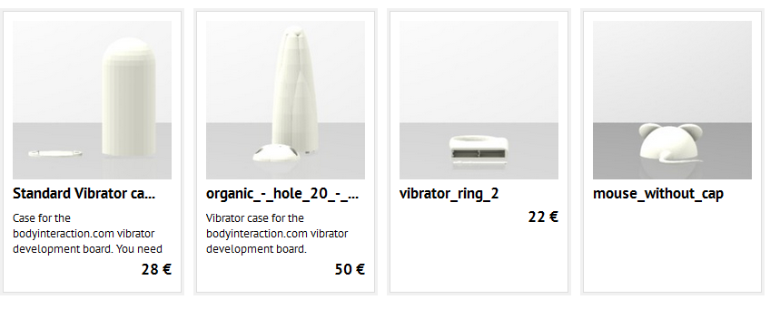
Print your vibrator case, visit our galleries and read the quick start guide
The case for the body interaction vibrator development board are printed with a 3d printer. There are two possibilities.
(1) You can use a printing service like Shapeway or Sculpteo. Sculpteo has the advantage that they offer food safe material. This means there are no risk if you apply the case to your skin or even insert the case. Follow this Link to the Public Sculpteo Library. The library offers 3d views, material, color, finishing configuration and price calculation (there are no surcharges for the designer.):
http://www.sculpteo.com/de/embed/gallery/?click=order&designer=south
 (2) You can print the design on your own 3d printer at home. If you don’t have one you could go to your next Fablab or Hackerspace and ask if you could us the printer. You need a STL file which can be downloaded from http://www.thingiverse.com/south/designs
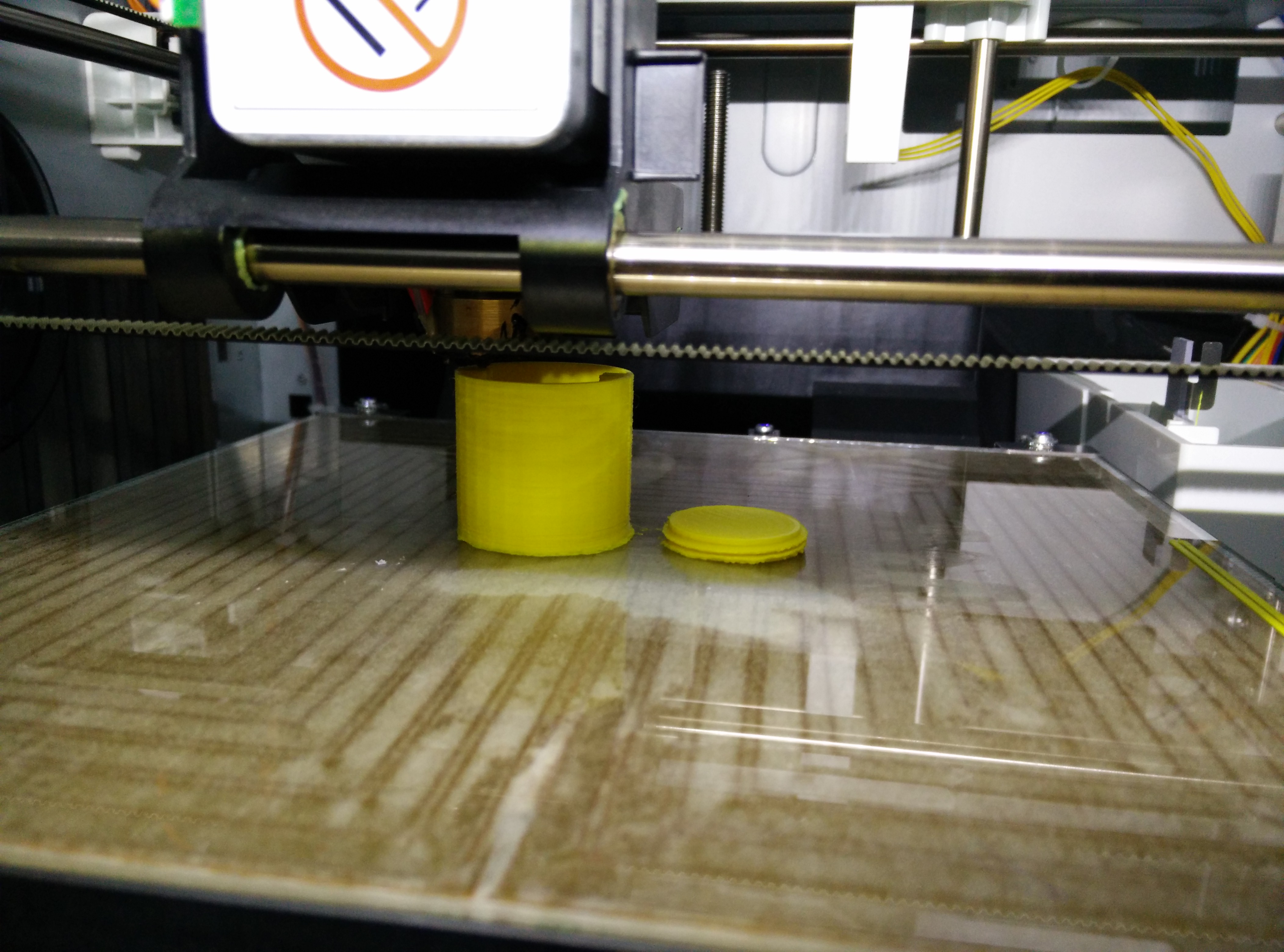 After printing the case you can assemble the body interaction vibrator development board. In the blog you will find several videos which explain the assembling. For a quick reference please download our guide: quickstartguide-bodyinteraction1
