
This the third part of the tutorial which has the following parts:
part 1: Basic Node for the Internet of Sex Toys
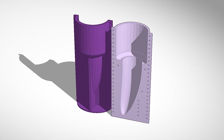
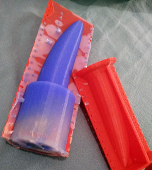
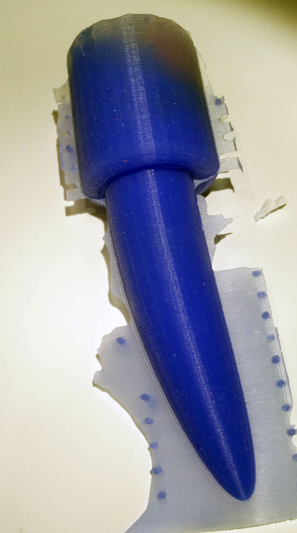
part 2: Molding the Basic Node
part 3: Software for the Basic Node
For the basic node a simple software realizes all features like Mqtt communication, Web server, basic web user interface, reading data from the accelerometer. Please use the code at github and send request over github. Now the imported parts of the code are explained.
To communicate with the IOT Mqtt is used (read more here). This is a fast protocol for data transmission. Therefore we need a Mqtt server. You can install one on your local computer or use a cloud-based Mqtt server. We use the free CloudMqtt. The following variables must be initiated with the data of your server. Please get your own account at CloudMqtt or use my server (but don’t spam it, please). Please remember: Transmission is not encrypted, everybody can read it.
const char* mqtt_server = "m12.cloudmqtt.com";
uint16_t mqtt_port = 15376;
const char* mqtt_user = "nvcuumkf";
const char* mqtt_password = "C-X6glwisHOP";
We have now 7 different modes. In each mode the basic node behaves different.
const int offMode = 0;
const int maxMode = 1;
const int sinusMode = 2;
const int motionMode = 3;
const int constantMode = 4;
const int listenMode = 5;
const int listenAndMotionMode = 6;
In off mode the basic node is off, in max mode the vibration is maximum. In sinus mode the vibration speed is altered according to a sinus curve.

Web user interface of the basic node
In motion mode the vibration changes according to the movement of the basic node. When moved fast the speed goes up, when moved slowly or movement stops, the speed goes down. In constant mode any vibration speed can be set to any strength. This feature is only available by Mqtt messages eg. from the IOT node-RED user interface. The listen mode is still experimental. In this mode the speed will be changed by OTHER basic nodes. Finally in the listenAndMotionMode the speed is changed by movements of the basic node and by other nodes. This feature was already available with the body interaction 1 development board as standard mode!
The basic node starts a web server (see image). A web page is generated which build up the user interface. There are buttons for every mode. In addition the speed and the battery power is displayed. This is done in this function:
void generateWebpage() {
The next lengthy procedure is this:
void mqttCallback(char* topic, byte* payload, unsigned int length) {
This is a call back function which is executed whenever a Mqtt message comes in. It parses the Mqtt message which is in the popular JSON format. The commands which are communicated within JSON are explained here. In principle there is a command for every mode, when the command “set mode to off” is send the mode is set to offMode.
In the setup() part of the code you will find a lot of lines like that:
httpServer.on("/MOTOR=MAX", []() {
They corresponds to the generateWebpage() function. When say the max button on the web page is pressed than the affiliated httpServer function is executed. So for every button on the webpage you need a corresponding httpServer function to implement the functionality. In this case (MOTOR=MAX) the mode is set to the constant speed maxMode.
Finally in the loop section of the code the following functions are implemented:
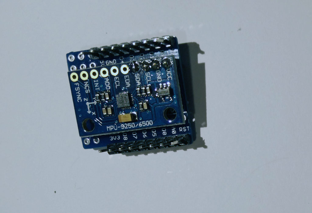
- reading the accelerometer data
- change the vibration motor speed according to the mode
- generate a new JSON message which is send out via Mqtt
- do the timing
Not mentioned is the OTA (over the air update) function, which is integrated in the code.
Node-RED
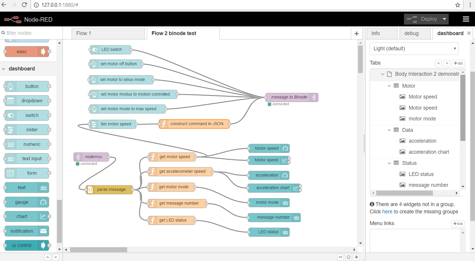 For controlling the toy via the internet you can use node-Red. You can find the code at github via this link.
The flow is explained here and here.


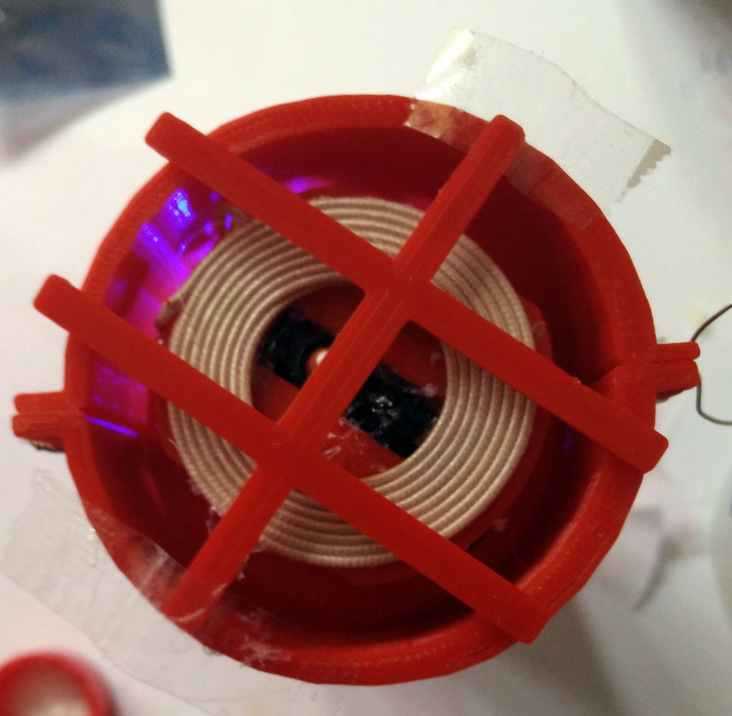


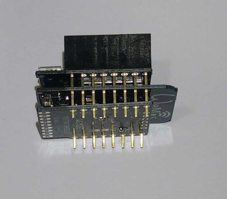


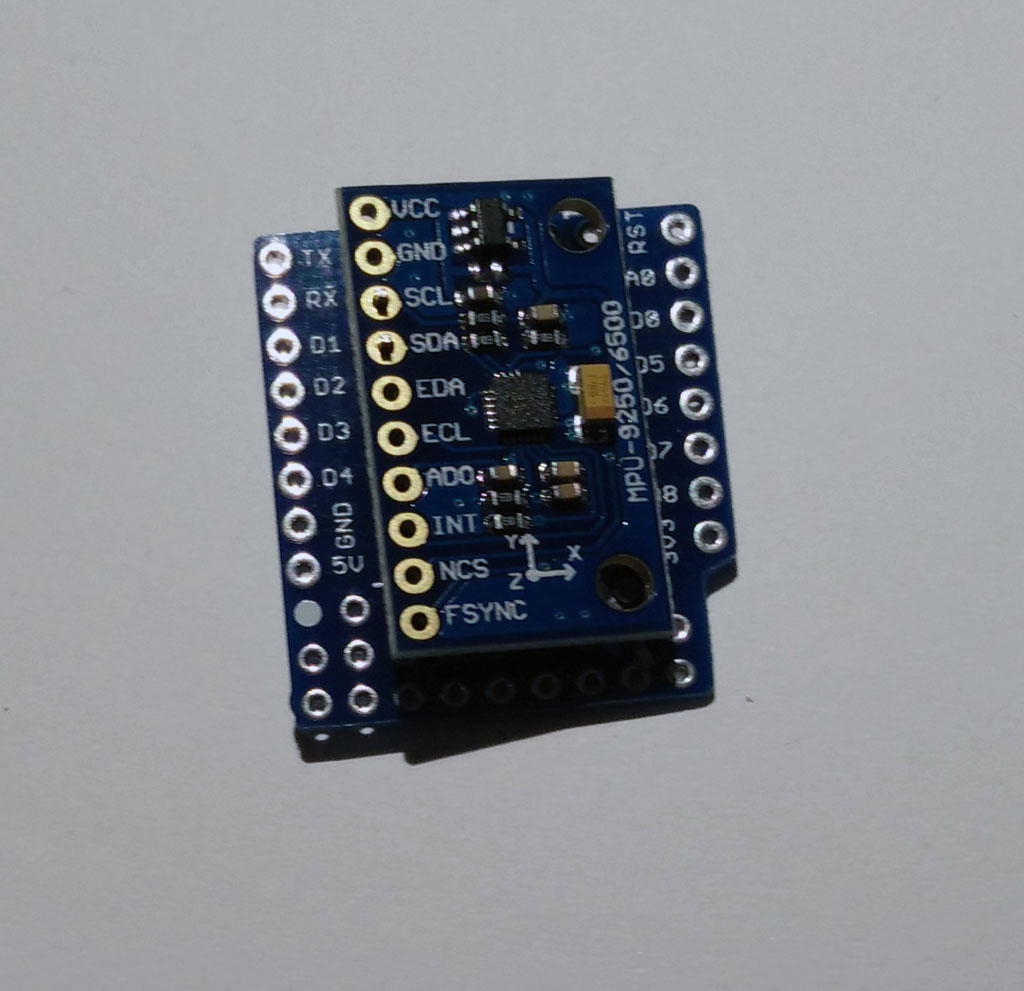
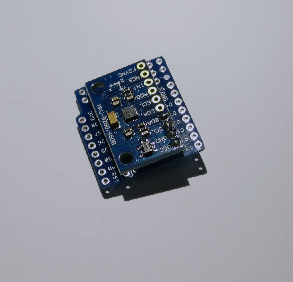
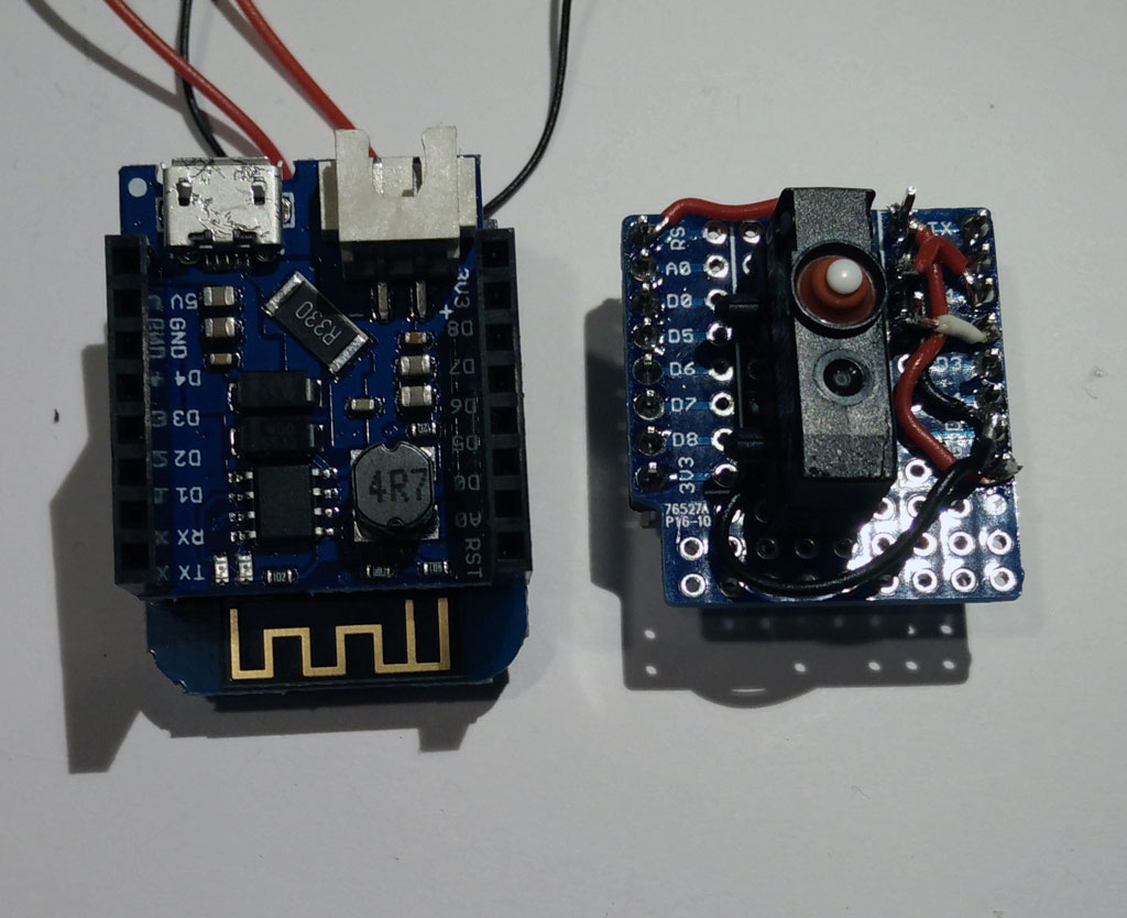


 Now stack the protoytping board on top of the battery shield. And connect the battery.
