
The UK-based Startup magazine is looking for the best female startup company. Touchy-Feely is on the short list and you can vote for them. Touchy-Feely develops educational electronic sex toy kits accompanied by workshops on basic and advanced sex toy topics. The founders have committed to building the funniest, most educational and pleasurable DIY electronics and coding kit out there.…
Category: Arduino
Controlling two BI2 with Blynk
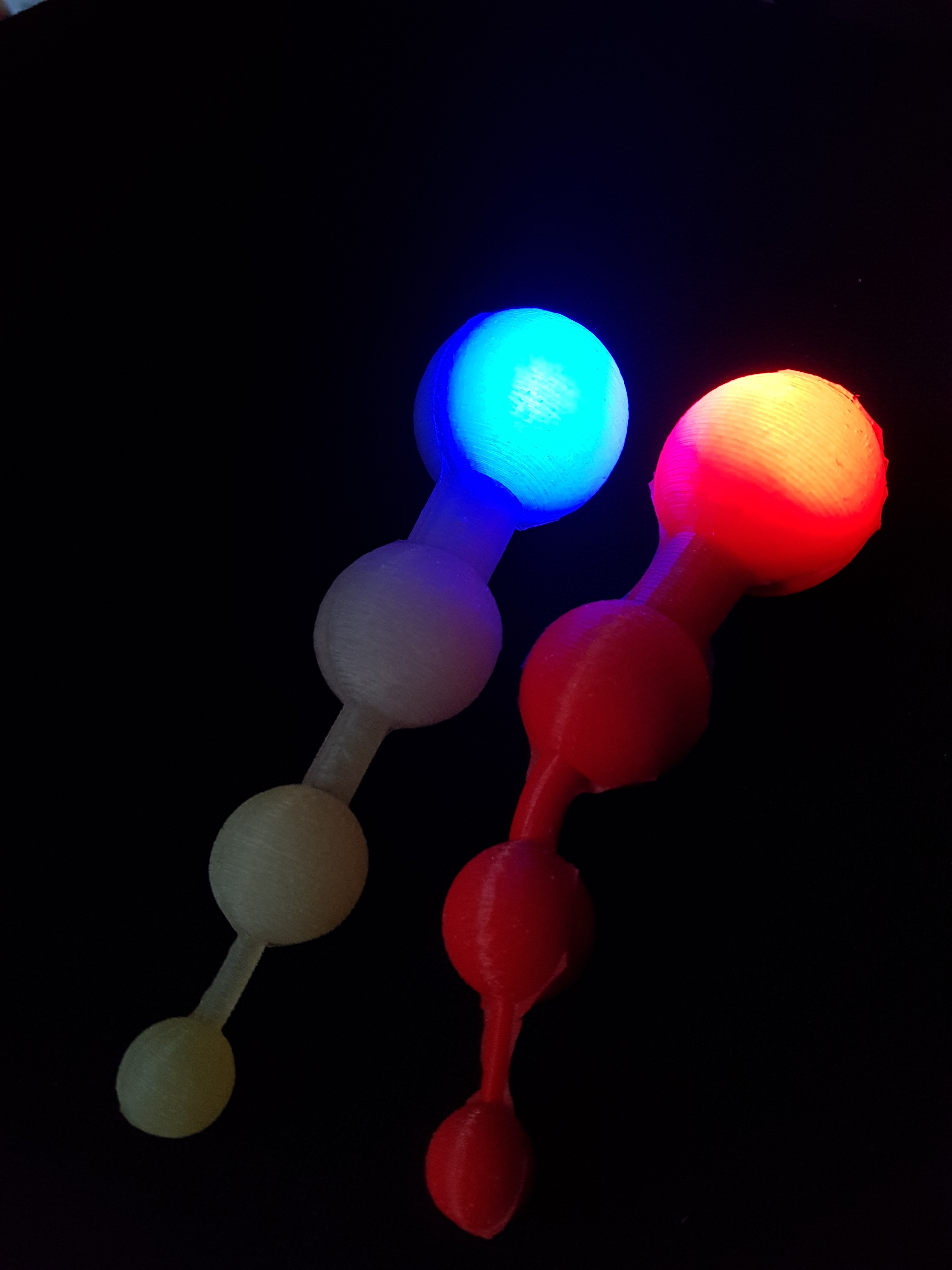
Controlling more than one body interaction 2 boards is very easy.
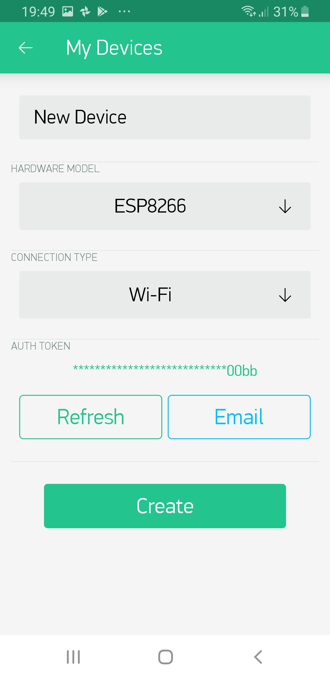
At first go to project settings in the Blynk app, go to devices and add a new device.

Then create a new device and press Email. You will get an Email with the auth token.
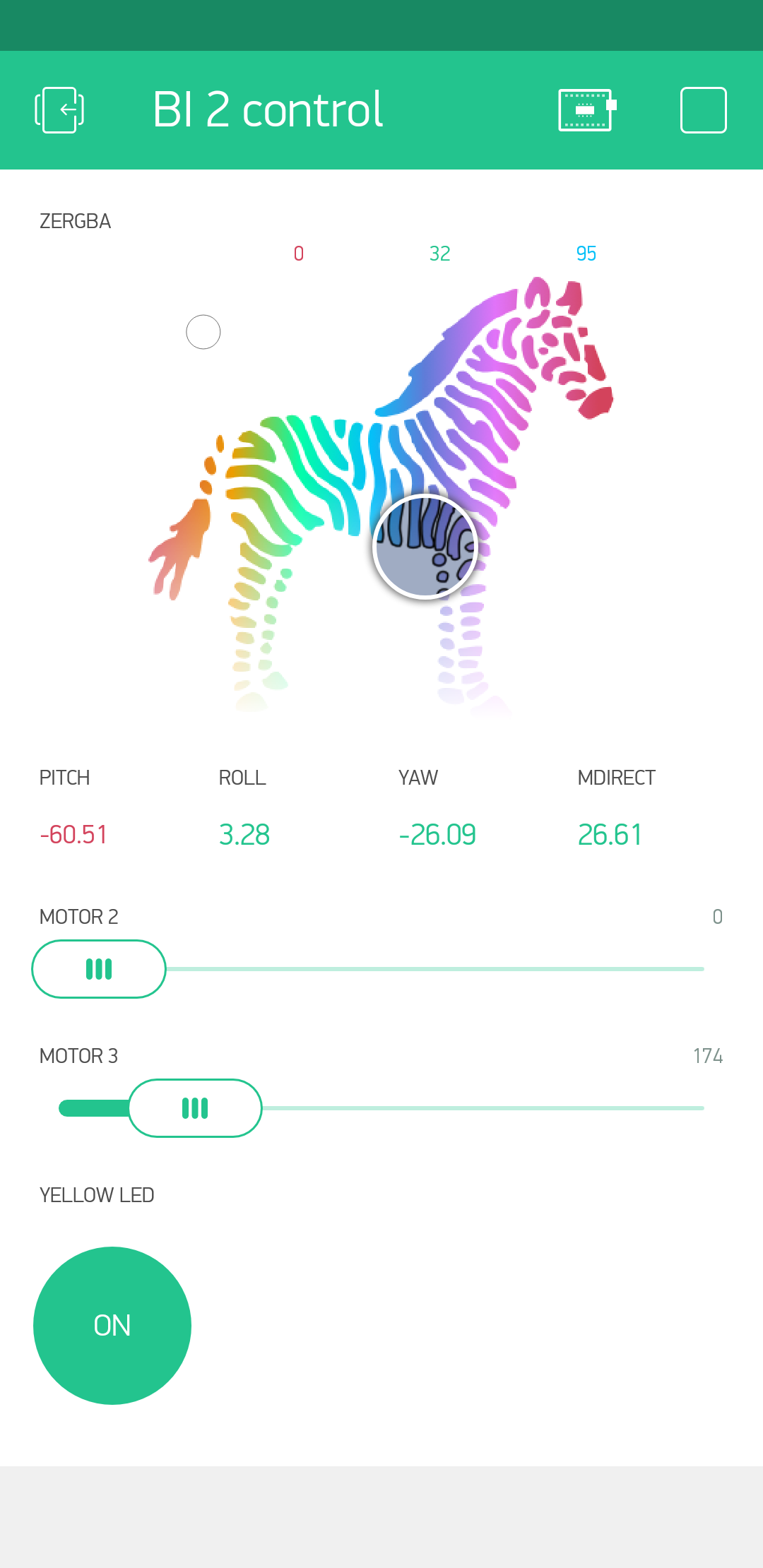
Add slider widget for the motor and another ZEGBRA widget for controlling the LED. For LED select a new virtual pin, e.g. V10.
You can start with this ready made app:
- Download Blynk App: http://j.mp/blynk_Android or http://j.mp/blynk_iOS
- Touch the QR-code icon and point the camera to the code below

It should look like this:

Then reuse the code from this blog post.
Change the following:
- fill-in the auth token which you got per Email
- change the name of the virtual pin V0 (for the LED) to e.g. V10 (the same name as in the Blynk app)
That’s it!
Programming the body interaction 2 (BI2) with Blynk part 1
This in an intro to using and programming the BI2 with the Blnyk app. Read here how to set up Arduino. For a more general basic intro (based on the body interaction 1 board) read here.
Pins
 The communication between app and BI2 microcontroller is realized by pins. The idea is very easy: Each widget in the Blynk app is connected to a physical pin of the microcontroller. Every microcontroller has several pins where you can connect other electronic parts like a LED or a vibration motor. For each pin you have to configure if it is a output or input pin. Output pins are for controlling actuators, like LED, motor or display. Input pins are connected to sensors, like buttons, temperature sensors, acceleration sensor. In addition each pin can be digital, analog or virtual.
Digital output pins can only set the actuator to on or off e.g. turning the LED on or off. Analog pins can set the actuator to a specific value in a given range. Usual this in done in the range [0..255] or [0..1023]. For a motor 0 will set the motor off, 50 may be make the motor move very slowly and 255 will be full speed. An analog output pin is sometimes called PWM. (PWM is a method to simulate an analog signal with a sequence of digital on/off signals.)
Digital input pins can read the position of a button (on/off). Analog input pins can read a value in a given range, e.g. the acceleration in the X-axis or the temperature.
So what you have to do to connect a widget to a pin? Just set the widget (e.g. on/off switch widget) to the pin you want to set on/off (e.g. a pin which is connected to a LED). That’s all. No programming required. All you need is this small program which must be uploaded to the microcontroller with the Arduino IDE.
The body interaction 2 use the ESP8266 microcontroller. There are 16 pins, all could be used as digital or analog, input or output. But only pin 12 and 13 are free to use (the rest if for internal communication). Pin 14 is connected to the LED WS2821B.
The Arduino sketch
The first 3 lines are for configuring Blynk and using two libraries. The 3 variables auth, ssid and pass are defined. (The variables are from thy type char (=character) and in this case it is not only one character but an array which you can see by the “[” and “]”. Here you have to add your AUTH token from the Blynk app, and SSID and password from your local WLAN/WIFI.
#define BLYNK_PRINT Serial
#include <ESP8266WiFi.h>
#include <BlynkSimpleEsp8266.h>

char auth[] = "XXXXXXXXXXXXXXXXXXXXXXXXXXX";
char ssid[] = "XXXXXXXX";
char pass[] = "XXXXXXXX";
Each Arduino program consists of a setup and a loop procedure. The setup is called only one time when the microcontroller is started (or connected to a battery). It is used to initialize the microcontroller, in this case Blynk is started. The loop will be called indefinitely and all statements are executed in the given order. To get Blynk running you have to call Blynk again and again (“Blynk.run();”). According to the Blynk manual, you should not add a delay() function here, because this could disturb the communication between the app and the microcontroller.
void setup() {
  Blynk.begin(auth, ssid, pass);
}

void loop() {
  Blynk.run();
}
Virtual pins
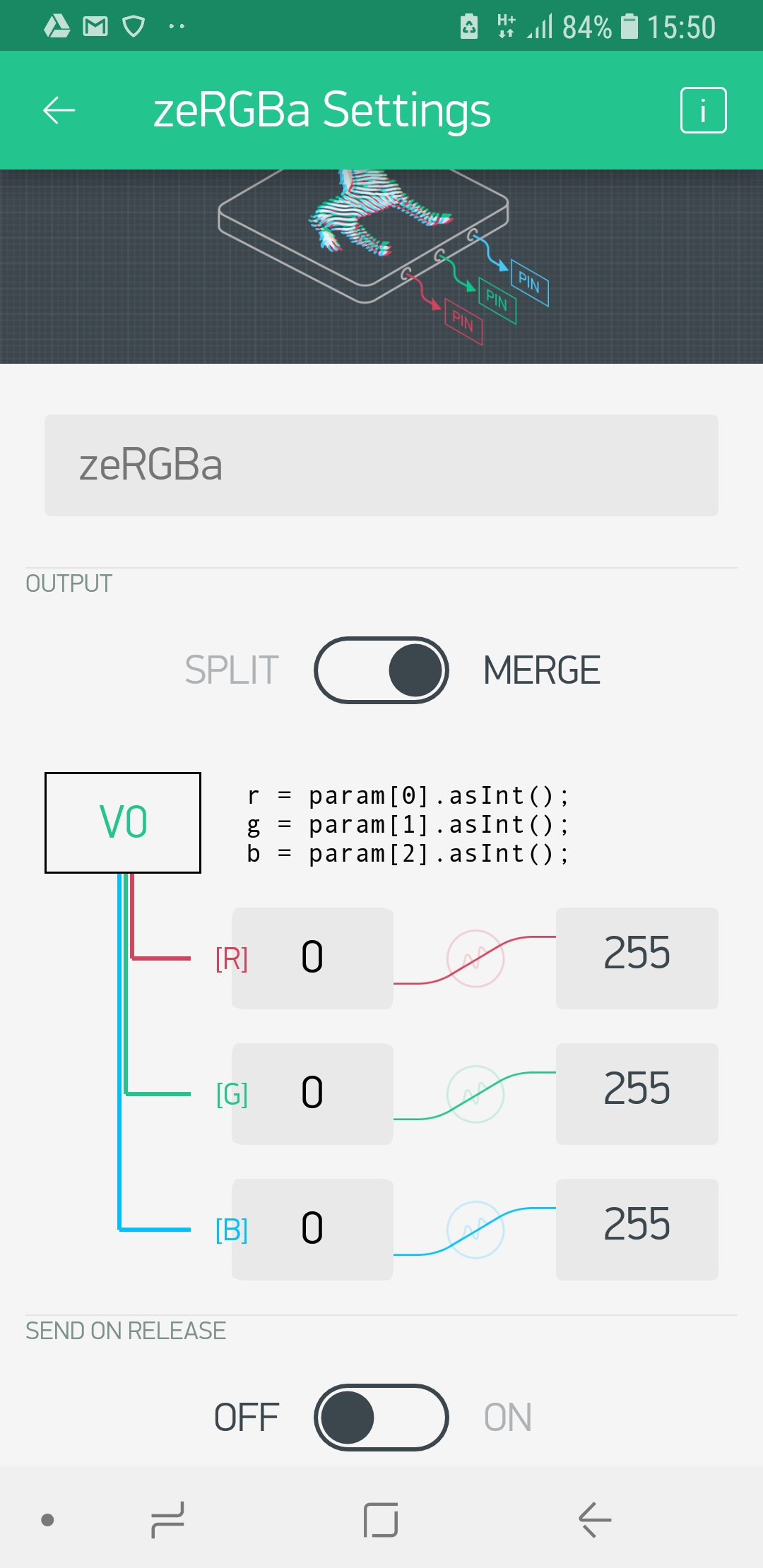 So far communication is only possible with physical pins. But how can you exchange other information? Maybe you want to tell the microcontroller to “shut up immediately”, or you want to play a given vibration pattern like a sinus curve. For this you can use “virtual pins”. (IMHO there is no reason to call this mean of data exchange “virtual” and it is has nothing to do with a pin. You can call it a variable or channel for data exchange.) The zeRGBa widget is a good example. The color of the LED is controlled by 3 values, the amount of red, green and blue color. This 3 values can be connected to one virtual pin (“V0”) and then they will be transmitted to the microcontroller. To change the color of the LED you have to program the microcontroller to read out the amount of each color and set the LED to the appropriate value.
We will demonstrate virtual pins with the LED. The WS2821B LED is connected to pin 14, but you cannot control the LED directly by setting the pin to a given value. This is done by a library which controls the LED.
First we have to include the library, we use FastLED.
#include "FastLED.h"
Then we have to tell how many LEDs we have (you can put several of them in a chain). The BI2 has only one on board (but you can add more).
#define NUM_LEDS 1 // number of LEDs
The you have to tell to which physical pin the LED is connected (14). Finally you have to set up a (instance of an) object “CRGB” for the LED where all relevant data is hidden.
#define DATA_PIN 14 // pin for LED
CRGB leds[NUM_LEDS]; // define the array of leds
Now comes the more difficult part. The zeRGBa widget has 3 values (one for red, one for green, one for blue) and all are put in the virtual variable V0.
We have add a new function called “BLYNK_WRITE(V0)”. To get the first value we have to read out “param[0]”, for the second “param[1]” etc. We want to store this first value in a variable “i” of the type integer. To assure that param[0] is also from the type integer we add “.asInt()”. The value for red is put in variable i, green in j and blue in k.
BLYNK_WRITE(V0) {
  int i = param[0].asInt();
  int j = param[1].asInt();
  int k = param[2].asInt();
}
Now we have to tell the function BLYNK_WRITE what to do with the values i, j an k. This is done by using the method setRGB which is attached to the LED (which is number 0)
leds[0].setRGB(j,i,k);
Now we can make changes to other LEDs (if we have more than one). If you are ready you have to tell the LED to show the new color.
FastLED.show();
In addition a new statement has to be added to setup the LED within the setup part.
void setup() {
  FastLED.addLeds<WS2812B, DATA_PIN, RGB>(leds, NUM_LEDS);
  [...]
Now we can put everything together the script will look like this:
/*************************************************************
Controling the body interaction 2 board with the Blynk app
*/

#define BLYNK_PRINT Serial
#include <ESP8266WiFi.h>
#include <BlynkSimpleEsp8266.h>

// Auth Token infor the Blynk App.
char auth[] = "XXXXXXXXXXXXXXXXXXXXXXXXXXX";

// Your WiFi credentials.
char ssid[] = "XXXXXXXX";
char pass[] = "XXXXXXXX";

// Library for controlling the WS2821B (Neopixel) LED or LED strip
#include "FastLED.h"
#define NUM_LEDS 1 // number of LEDs
#define DATA_PIN 14 // pin for LED
CRGB leds[NUM_LEDS]; // define the array of leds

// This function set the LED color according to the selected RGB values in the app.
// RGB values are controlled in the app with zeRGBa widget
// values are stored in the virtual pin V0
// V0 consists of 3 values for Red, Green, Blue
BLYNK_WRITE(V0) // set LED RGB color values
{
  int i = param[0].asInt();
  int j = param[1].asInt();
  int k = param[2].asInt();
  leds[0].setRGB(j,i,k);
  FastLED.show();
}

void setup()
{
  // init LEDs
  FastLED.addLeds<WS2812B, DATA_PIN, RGB>(leds, NUM_LEDS);

  // connect to Blynk
  Blynk.begin(auth, ssid, pass);
}

void loop()
{
  Blynk.run();
}
Do you like this, do you need this, do you understand this? Tell me jacardano@gmail.com
The new BI2 black vibrator development board
The new black BI2 board is ready. I have a few assembled boards ready for shipping. Have a look at www.tindie.com
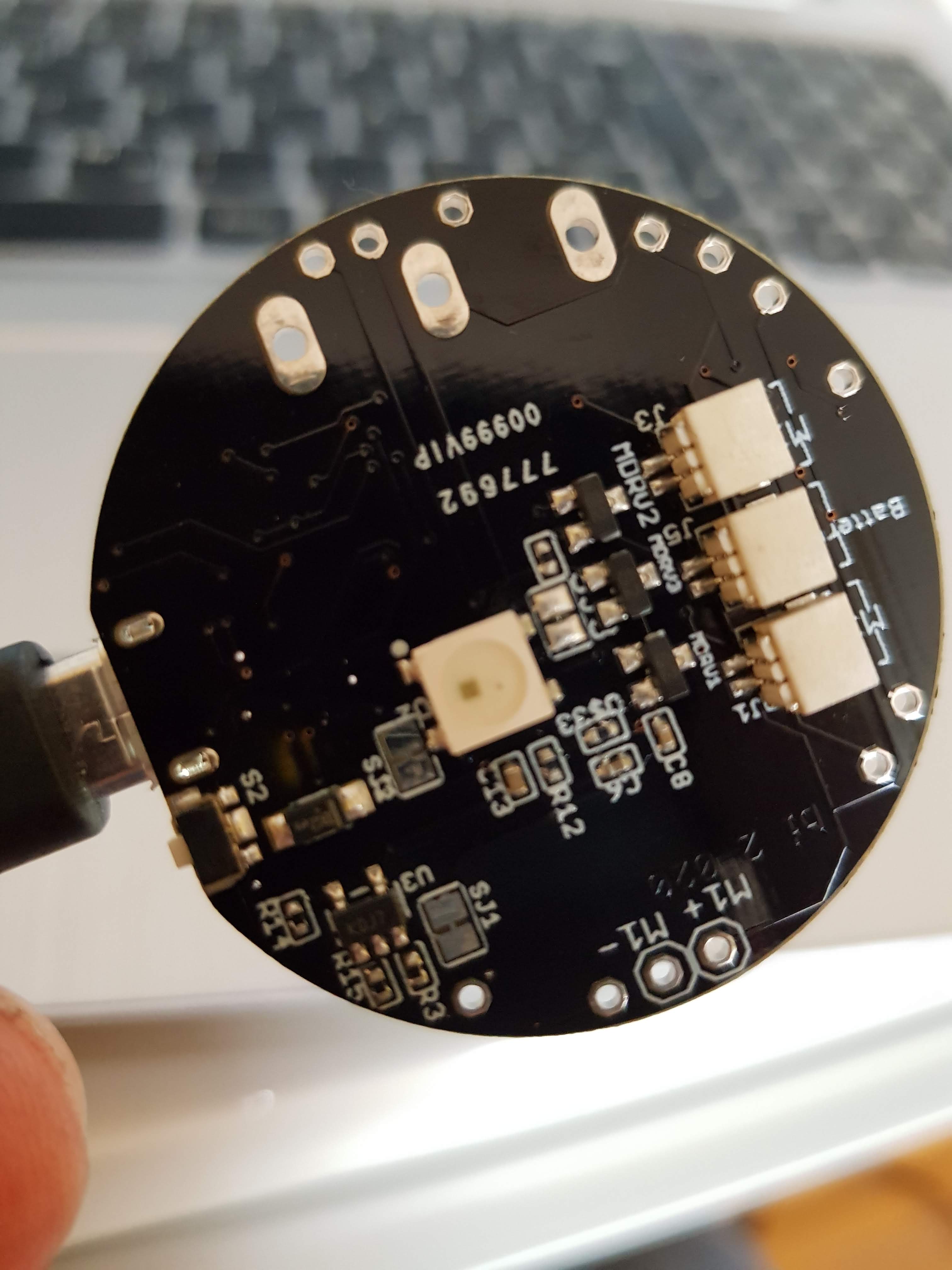
3 JST 1mm plugs (battery, motor 2, motor 3), LED, reset button, M+/M- is for motor 1

JST 1mm plug for motor 1, alternative RESET button
Features
- ESP8266 Microcontroller with WLAN
- MPU9250 (accelerometer, gyroscope)
- LiPo battery charging
- 3 motors can be connected (simple motor driver circuits)
- 1 WS2812B LED – a colourful LED (16 Mill. colours). They are commonly known as Adafruit Neopixel – a strip or a ring of individual programmable LEDs (when use the WS2812B only two motors can be connected)
- design based on the great Adafruit Feather Huzaah ESP8266
- vibration motors and LiPo battery can be easily connected with JST 1mm connectors
- two reset buttons (the button next to the USB connector can be overmolded)
- USB connector for battery charging and code uploading
- programmable with the Arduino IDE or NodeMCU
- white LED for indicating charging
- standard LED (yellow) on GPIO00
- round 40mm diameter

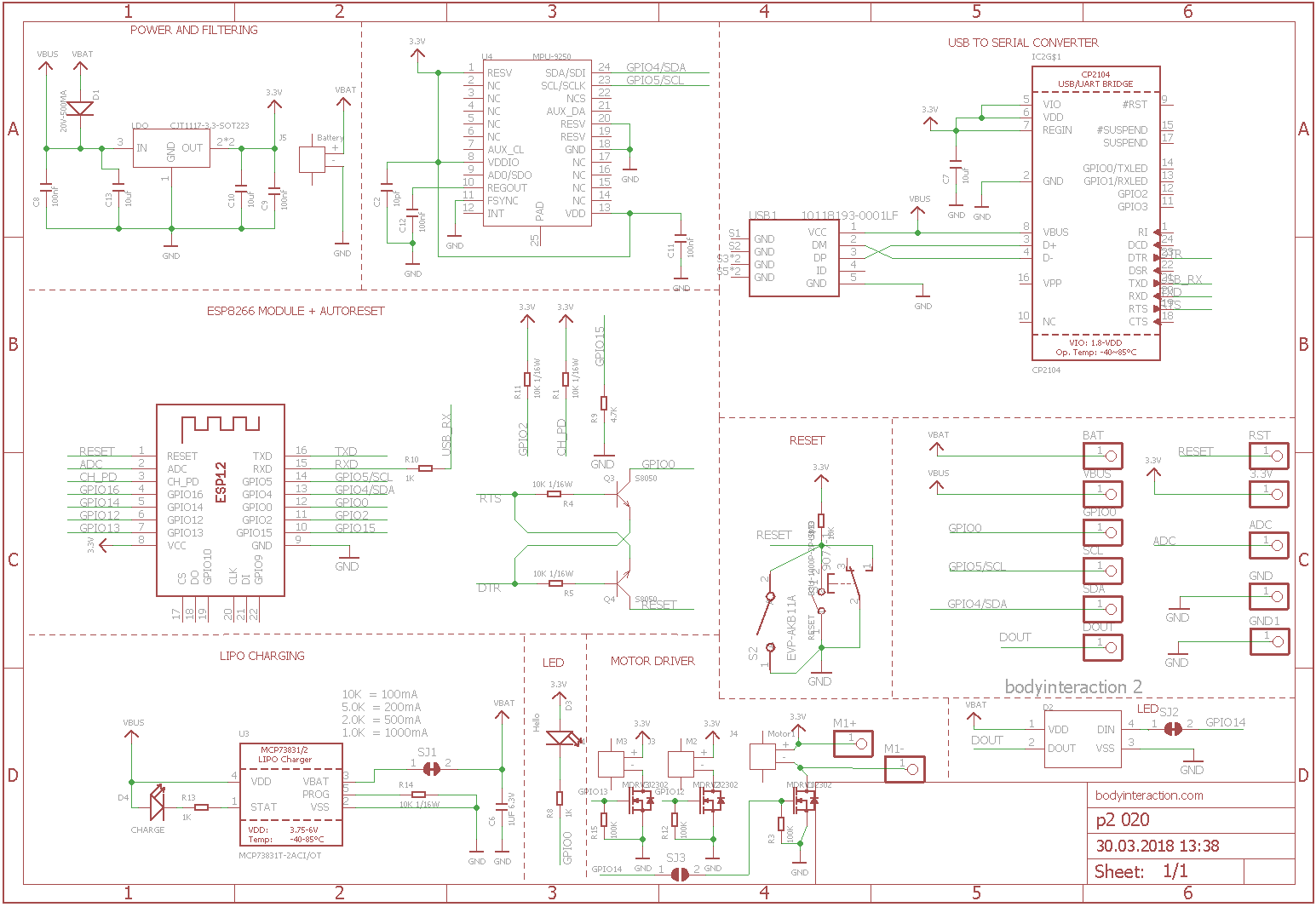
There are 3 free GPIO ports. Standard layout are for driving 2 motors (GPIO 12 = M2, GPIO 13 = M3) and 1 LED (GPIO14). Alternatively you can use 3 motors (GPIO12,13,14) but no LED.
Standard: SJ2 not connected, SJ3 connected
Alternative: SJ2 connected, SJ3 not connected
Here is the schematic which is adapted from Adafruit.
References:

Basic Node for the Internet of Sex Toys – part 3: software
This the third part of the tutorial which has the following parts:
part 1: Basic Node for the Internet of Sex Toys
part 2: Molding the Basic Node
part 3: Software for the Basic Node
For the basic node a simple software realizes all features like Mqtt communication, Web server, basic web user interface, reading data from the accelerometer. Please use the code at github and send request over github. Now the imported parts of the code are explained.
To communicate with the IOT Mqtt is used (read more here). This is a fast protocol for data transmission. Therefore we need a Mqtt server. You can install one on your local computer or use a cloud-based Mqtt server. We use the free CloudMqtt. The following variables must be initiated with the data of your server. Please get your own account at CloudMqtt or use my server (but don’t spam it, please). Please remember: Transmission is not encrypted, everybody can read it.
const char* mqtt_server = "m12.cloudmqtt.com";
uint16_t mqtt_port = 15376;
const char* mqtt_user = "nvcuumkf";
const char* mqtt_password = "C-X6glwisHOP";
We have now 7 different modes. In each mode the basic node behaves different.
const int offMode = 0;
const int maxMode = 1;
const int sinusMode = 2;
const int motionMode = 3;
const int constantMode = 4;
const int listenMode = 5;
const int listenAndMotionMode = 6;
In off mode the basic node is off, in max mode the vibration is maximum. In sinus mode the vibration speed is altered according to a sinus curve.

Web user interface of the basic node
In motion mode the vibration changes according to the movement of the basic node. When moved fast the speed goes up, when moved slowly or movement stops, the speed goes down. In constant mode any vibration speed can be set to any strength. This feature is only available by Mqtt messages eg. from the IOT node-RED user interface. The listen mode is still experimental. In this mode the speed will be changed by OTHER basic nodes. Finally in the listenAndMotionMode the speed is changed by movements of the basic node and by other nodes. This feature was already available with the body interaction 1 development board as standard mode!
The basic node starts a web server (see image). A web page is generated which build up the user interface. There are buttons for every mode. In addition the speed and the battery power is displayed. This is done in this function:
void generateWebpage() {
The next lengthy procedure is this:
void mqttCallback(char* topic, byte* payload, unsigned int length) {
This is a call back function which is executed whenever a Mqtt message comes in. It parses the Mqtt message which is in the popular JSON format. The commands which are communicated within JSON are explained here. In principle there is a command for every mode, when the command “set mode to off” is send the mode is set to offMode.
In the setup() part of the code you will find a lot of lines like that:
httpServer.on("/MOTOR=MAX", []() {
They corresponds to the generateWebpage() function. When say the max button on the web page is pressed than the affiliated httpServer function is executed. So for every button on the webpage you need a corresponding httpServer function to implement the functionality. In this case (MOTOR=MAX) the mode is set to the constant speed maxMode.
Finally in the loop section of the code the following functions are implemented:
- reading the accelerometer data
- change the vibration motor speed according to the mode
- generate a new JSON message which is send out via Mqtt
- do the timing
Not mentioned is the OTA (over the air update) function, which is integrated in the code.
Node-RED
 For controlling the toy via the internet you can use node-Red. You can find the code at github via this link.
The flow is explained here and here.
Internet of (sex) things – part 4: Building a sex toy dashboard with Node-RED
In the fourth part of the tutorial we explain the development of a dashboard for our sex toy.
The series has 4 parts:
part 1: Exploring the internet of (sex) things
part 4: Building a sex toy dashboard with Node-RED
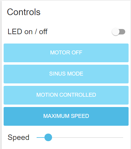
The dashboard is used to visualize certain data eg. the speed of the vibration motor and the movements of the vibrator. In addition it can have some control elements eg. for changing the vibration pattern.
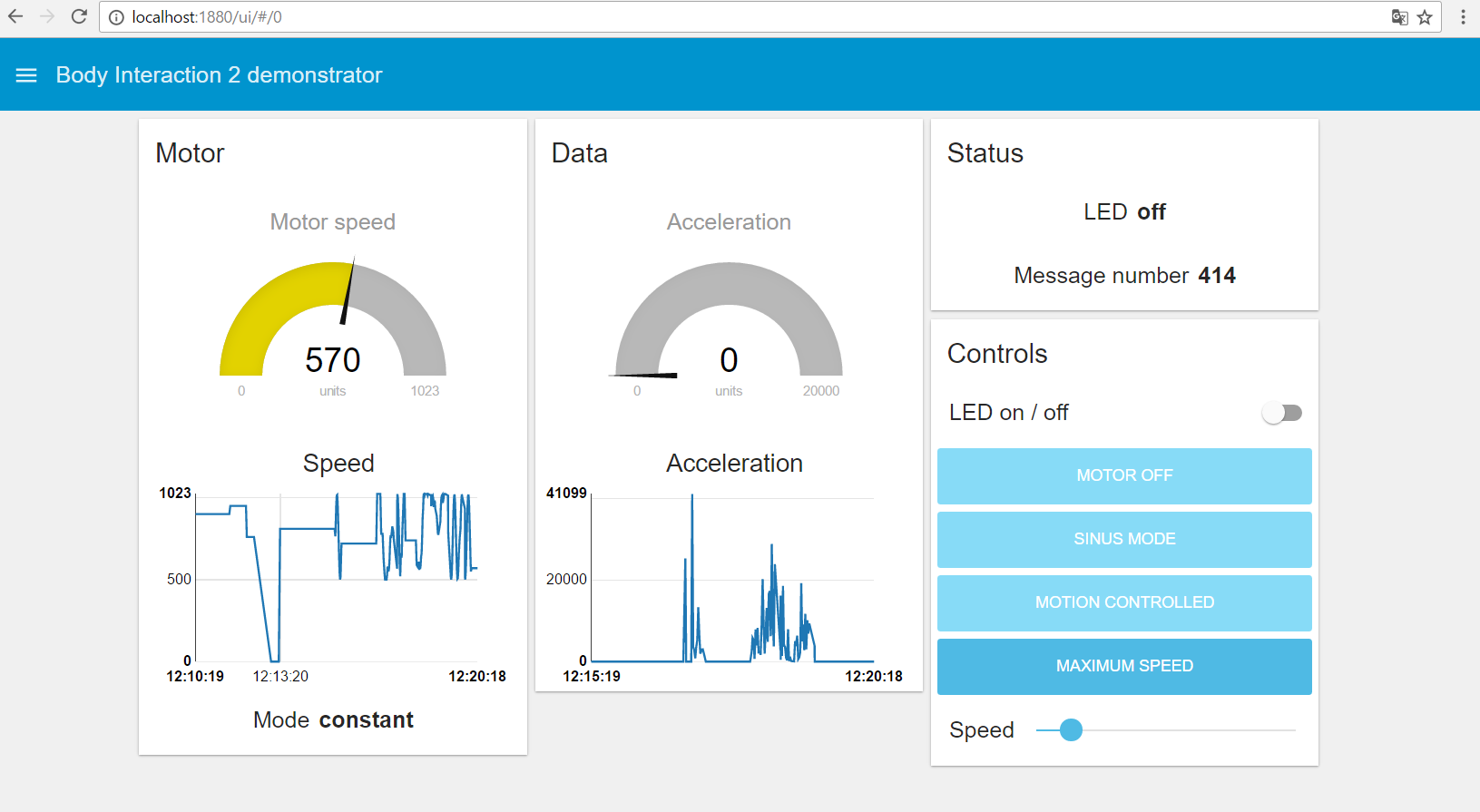
The window above is called a tab. You can have multiple tabs. The Motor, Data, Status and Controls – windows are called groups. The Controls – group has buttons to set the motor mode. In addition there is a slider which will set the motor to a constant speed. And there is an on/off button for the LED.
You have to install the Node-RED dashboard. Therefore you need at least version 0.14 of Node-RED. At the time this text was written the standard Node-RED installation is version 0.13 which is not sufficient for the dashboard.
Therefore check your Node-RED version. If it is equal or better than 0.14, skip this step:
- Download & unzip the latest version from github (eg. https://github.com/node-red/node-red/releases/tag/0.15.2).
- Now change to newly created directory eg “node-red-0.15.2”
- On Windows: Start a command shell in adminstration mode
- Execute “npm install” to install Node-RED.
If your Node-RED version is 0.14 or better install the dashboard:
- Download the Node-RED Dashboard: http://flows.nodered.org/node/node-red-dashboard
- Use the command shell and enter “npm install node-red-dashboard”
- Enter “node red”
- Enter the URL http://127.0.0.1:1880/ in your browser
Some remarks:
- If you don’t want to install Node-RED on your computer you could use the FRED Node-RED service. It has similar dashboard nodes and a lot more. It is free for a limited number of node.
- There is a very good tutorial which will explain different possibilities for creating a dashboard: http://noderedguide.com/index.php/2016/05/17/lecture-7-dashboards-and-ui-techniques-for-node-red/
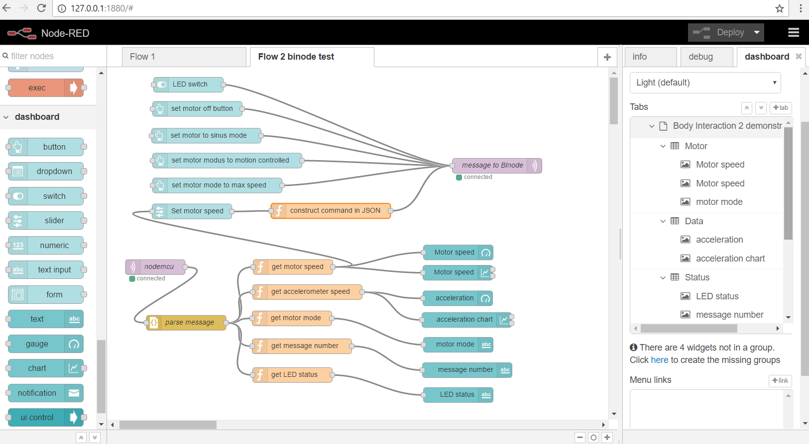
Let’s start and have a look at the new Node-RED interface: On the left side you will find the dashboard or user interface nodes. And on the right side there is new dashboard – tab. It contains all dashboard nodes which are used in the flow ordered hierarchical.
But where is the dashboard? Just open your browser and go to one of the URLs:
http://localhost:1880/ui/#/0 or
http://127.0.0.1:1880/ui/#/0
How can I get all the flows? You can download all flows here: bi-ui-node-red. Unzip the file and you will get a text file. Open the text file in an editor. Select the text and copy it to the clipboard.
Now we will explain two flows in detail.
Now go the Node-RED window, open the menu (it is on the left top side), select Import -> Clipboard.
A new window will open where you can insert the text (CTRL+V). Then press the Import-button.

 The Arduino sketch was updated for the dashboard. Please download the Arduino sketch from here: iost-part4-v12. Unzip the file. Compile and upload to your hardware (see part 1 of the tutorial).
In the first flow we will receive some vibration motor sex toy data which are sent by the MQTT protocol. We will display the data using a gauge and a graph element.
Let’ start with the MQTT input node. There is nothing new. Just connect to the MQTT server and subscribe the topic “BIoutTopic2” – which the sex toy uses to send out data.
Now add the function node “JSON” which will parse the incoming message and places the result in “payload”.
But we want to know the motor speed only. Therefore we need a function node which passes the vibration motor speed as payload and deletes all other data. Please use the following JavaScript code:

To display the speed we need to more nodes. The gauge node  displays the actual speed. Connect the gauge node with the function node. You can add the range – the minimum and maximum value (0 and 1023).
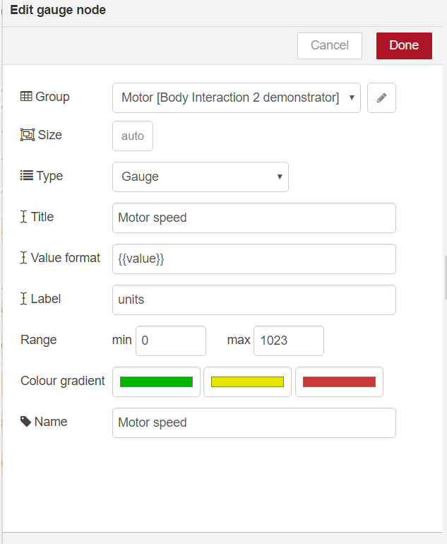
Now add a chart node  and connect it with the function node, too.
Next we want the chart node and the gauge node to be together as shown in the next image.
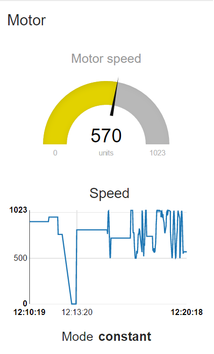
We have to make a group and put both nodes into the group. Have a look on the dashboard at the right side. Make a new group and move the gauge and chart node below the group called “Motor”.

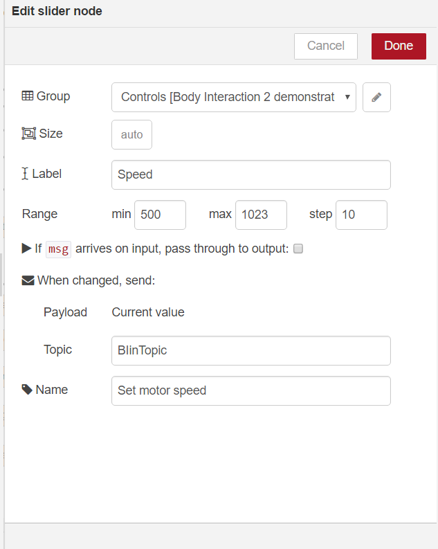
 Now we explain the second flow. It is used to send commands to the sex toy. We will use a slider to control the speed. But there is one problem: the slider should display the actual speed of the vibration motor. Therefore we manipulate the slider. To display the actual motor speed we have to move the slider appropriate to the actual speed. The slider will be part of the control group:
Now get the slider node and edit the node as follows:
Then connect the node with the “get motor speed” function which was introduced in the first flow.
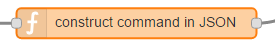 Finally comes the trick part. Get a new function node and connect it with the slider. This node will construct the JSON message which will be sent to the sex toy using MQTT. The JavaScript code of the function node is as follows:
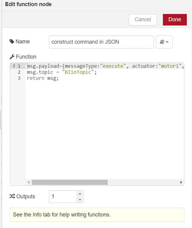
msg.payload={messageType:"execute", actuator:"motor1",
             actuatorMode:"constant", actuatorValue:msg.payload}
msg.topic = "BIinTopic";
return msg;
Now connect the function node with a new MQTT output node. Leave the topic empty as it will be passed from the input nodes:

Using Node-RED with the Node-RED dashboard we are able to make a user interface for our sex toy(s). We could easily display the motion of the sex toy as well as the vibration motor speed. You could argue that we had a (very simple) user interface already in part 1 of the tutorial, without having to use MQTT, Node-RED and the Node-RED dashboard. That’s true. But imagine you have several sex toys and want to control them. You could easily add a tab in Node-RED for each sex toy. Or you could build more sophisticated flows incorporating several sex toy. Why not interconnecting the vibrating necklace with a penis ring and one of the plugs or dildos?
There are a lot of flows and nodes already available at http://flows.nodered.org/. (Of course not in the sex toy domain)
Why not play music for a given sex toy vibrator mode? Or control the sex toy using another IOT device…
Internet of (sex) things – part 2: MQTT messages
In the first IOT tutorial we have shown how to build a sex toy based on a ESP8266 MCU.
There are two more parts of this tutorial series:
part 4: Building a sex toy dashboard with Node-RED
The ESP8266 is a microcontroller which can connect to the internet. You can write sketches with the Arduino IDE and connect a lot of actuator modules (like vibration motors, displays) and sensors (motion detection).
In the first approach a web server was installed on the ESP8266. Control was possible by browsing to the web server, which could be accessed by a computer or smart phone using the same WiFi Access Point (AP).

In this second tutorial we will connect the ESP8266 to the internet and publish and receive data as well as commands by internet.
Protocols
There are some protocols for publishing (sending) data. We use the MQTT protocol which is very fast and suited for short messages. In addition we need a MQTT server. We will send the ESP8266 data to the server. And the ESP8266 can receive data (or commands) from the server. Other services can connect to the MQTT server, too. In this tutorial we will use a MQTT client which can display the sex toy data and send commands to the ESP8266.

Sex toy data exchange format
A big disadvantage of commercial sex toys is their proprietary data exchange formats. Kyle Machutis developed buttplug.io a Cross Platform Framework for Sex Toy Control to overcome this issue.
For this IOT project we will use the JSON format which is a very simple way to exchange data:
This is an example for the message type “sensor”. It says that the fusioned sensor data of the “mps9250” MPU is 5657, the LED is off (0), the motor is in mode sinus curve (2) and the speed of the vibration motor is 766.
{"messageType":"sensor",
"sensor":"mps9250",
"fusionedData":5675,
"messageNumber":8,
"LEDstatus":0,
"motor1mode":2,
"motor1speed":766}
There are three message types: sensor, execute and message.
- Sensor is for publishing sensor data to everyone who is interested in that.
- Execute is for controlling a specific device, eg for turning the motor on.
- Message sends a text message to specific device. If the deviceID is not given it will be sent to all receivers,
For this project we need the
- hardware from part 1 of the IOT project
- the Arduino library JSON for parsing and encoding exchange data
- a library for sending and receiving MQTT data
- the mqtt-spy software to send and receive MQTT messages
- optional: a MQTTserver like mosquitto
Arduino JSON library
There is a great library which can parse and build JSON files. Here is the documentation: https://github.com/bblanchon/ArduinoJson
Please go into the Arduino library manager and install the JSON package.
Arduino PubSubClient library
In addition we need a package for sending and receiving MQTT messages. You will find the PubSubClient library in the library manager, too.
Documentation: https://github.com/bblanchon/ArduinoJson
You have to change the maximum length of a message. By default it is only 128. Search for the file PubSubClient.h and change MQTT_MAX_PACKET_SIZE to 1024. On my Win10 system the file is located at
C:\Users\...\Documents\Arduino\libraries\PubSubClient\src\PubSubClient.h
Change the following line:
// MQTT_MAX_PACKET_SIZE : Maximum packet size
 #define MQTT_MAX_PACKET_SIZE 1024
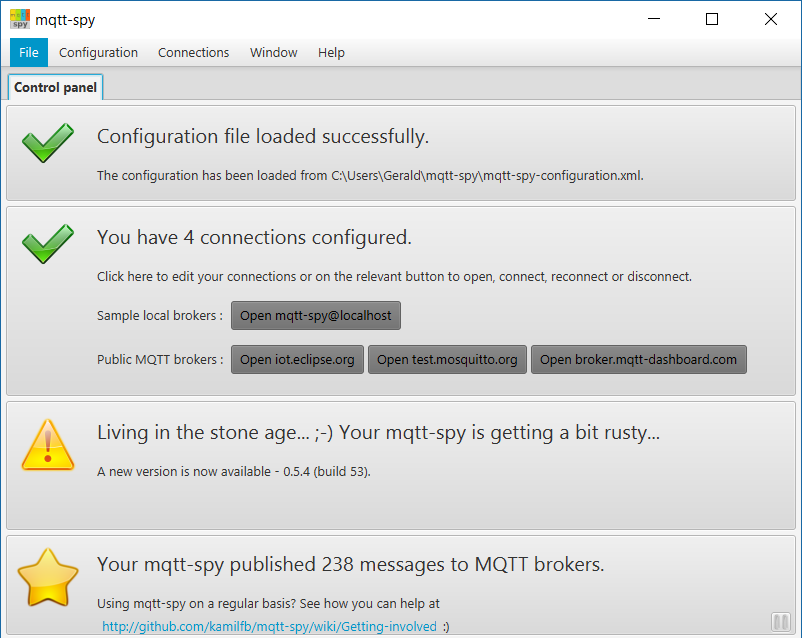
MQTT-SPY software
This is an excellent piece of software which can connect to a MQTT server and send and receive messages: mqtt.spy. We use it to test the connection from the ESP8266 to the mosquitto server and for debugging our vibrator toy control software on the ESP8266.
Download from https://github.com/kamilfb/mqtt-spy/wiki/Downloads
If you haven’t your own MQTT server, you can use the Mosquito test server (only for testing, don’t spam them). Start mqtt-spy and connect to “test.mosquito.org”.
Subscription of messages: To receive the messages from the ESP8266 you have to subscribe to a topic. Use the same topic as in the source code, eg. “BIoutTopic”. You have to select the “New”-tab in the subscription, a new window pops up. Enter “BIoutTopic”. Now you receive all messages from the ESP8266.
Publishing messages: In the upper part of the window enter “BIinTopic”. In the “data” field you enter commands which will be sent to the ESP8266. Enter the commands and press “Publish”.
 Try it out. Here are some examples:
JSON data exchange & command examples
Send message:
{
 messageType : "message",
 message : " Hello world!"
 }
Send Command – LED on:
{
 messageType : "execute",
 actuator : "LED",
 actuatorValue : 1
 }
Send command – motor1 modus is set to sinus curve vibration pattern
{
 messageType : "execute",
 actuator : "motor1",
 actuatorMode : "sinus"
 }
Send Command – set motor speed to 1000.
{
 messageType : "execute",
 actuator : "motor1",
 actuatorValue: 1000
 }
Send command – set motor1 off.
{
 messageType : "execute",
 actuator : "motor1",
 actuatorMode: "off"
 }
Message type “sensor”: this is for publishing sensor data of a sex toy (eg. position in 3d space, movement data, vibration pattern in use). These data can be received by other sex toys for vibration adjustment and synchronization of the vibration speed .
{
 messageType : "sensor",
 sensor: "mps9250",
 fusionedData: 10000,
 }
Remark: If it doesn’t work as expected, check the data field of the MQTT software. Paste & Copy doesn’t work as it should be and you may have to remove some redundant “{“-signs.
Code
The code is based on part 1. In the new code functions for publishing and receiving JSON data over MQTT are added.
Receiving and parsing incoming JSON files is done in “callback”. “callback” will be executed whenever a MQTT message comes in.
void callback(char* topic, byte* payload, unsigned int length) {
At first the incoming message is parsed and the result is stored in “root”. Now each entry in the JSON file can be accessed by assigning a new variable to root[entry]:
StaticJsonBuffer<500> jsonBuffer;
 JsonObject& root = jsonBuffer.parseObject(s);
 if (!root.success()) {
 Serial.println("parseObject() failed");
 }
 String messageType = root["messageType"];
Build and publishing JSON files is done in the loop. A JsonObject “root” is created and then each entry in the JSON file is added by an assignment to root eg: root[“messageType”] = “sensor”:
StaticJsonBuffer<500> jsonBuffer;
JsonObject& root = jsonBuffer.createObject();
root["messageType"] = "sensor"; // execute, message, sensor
For producing the JSON file there is “printTo” function. The JSON array of char must be formatted with the snprintf() function and then it can be published.
 root.printTo(outMsg, sizeof(outMsg));
 snprintf (msg,1000, "%s",outMsg);
 mqttclient.publish("BIoutTopic", msg);
Download the zipped and formatted code here: nodemcu-server-mqtt-iot.
In the next part of the tutorial we use Node-RED for visual programming our IOT sex toys.
Here is the complete source code for part 2 of the tutorial.
// bodyinteraction IOT project
// IOT sex toy prototype - control via browser and MQTT
#include <ESP8266WiFi.h>
#include <Wire.h>
#include <PubSubClient.h>
#include <ArduinoJson.h>

#define MPU9250_ADDRESS 0x68
#define MAG_ADDRESS 0x0C

#define GYRO_FULL_SCALE_250_DPS 0x00
#define GYRO_FULL_SCALE_500_DPS 0x08
#define GYRO_FULL_SCALE_1000_DPS 0x10
#define GYRO_FULL_SCALE_2000_DPS 0x18

#define ACC_FULL_SCALE_2_G 0x00
#define ACC_FULL_SCALE_4_G 0x08
#define ACC_FULL_SCALE_8_G 0x10
#define ACC_FULL_SCALE_16_G 0x18

const char* ssid = "ALICE-WLAN";
const char* password = "36s69c3756a65";
const char* mqtt_server = "test.mosquitto.org";

int ledPin = 0; // NodeMCU pad D3 = GPIO 0
int motorPin= 13; // NodeMCU pad D7 = GPIO 13
double sinusValue=0;

// define constants for four different vibration modes
const int offMode=0;
const int maxMode=1;
const int sinusMode=2;
const int motionMode=3;

int motorMode =offMode; //current mode
int motionVector = 0; //current fusioned motion
// Acceleration in x,y and z direction at t(ime)=1 and time=0
// Geroscop data
int16_t ax,ay,az,ax1,ay1,az1,gx,gy,gz,gx1,gy1,gz1;
int valueMotor; //vibrator motor speed 0-1023

WiFiServer server(80);

WiFiClient espclient;
PubSubClient mqttclient(espclient);
char msg[512];
char outMsg[512];

bool requesting=false; // is there a request eg button pressed on webpage

//timing of mqtt messages
long now=0;
long lastMsg = 0;


int value = 0;
int valueLED = LOW;

// This function read Nbytes bytes from I2C device at address Address.
// Put read bytes starting at register Register in the Data array.
void I2Cread(uint8_t Address, uint8_t Register, uint8_t Nbytes, uint8_t* Data)
{
// Set register address
Wire.beginTransmission(Address);
Wire.write(Register);
Wire.endTransmission();

// Read Nbytes
Wire.requestFrom(Address, Nbytes);
uint8_t index=0;
while (Wire.available())
Data[index++]=Wire.read();
}

// Write a byte (Data) in device (Address) at register (Register)
void I2CwriteByte(uint8_t Address, uint8_t Register, uint8_t Data)
{
// Set register address
Wire.beginTransmission(Address);
Wire.write(Register);
Wire.write(Data);
Wire.endTransmission();
}


// Return the response /generate webpage
void generateWebpage(WiFiClient espclient) {
espclient.println("HTTP/1.1 200 OK");
espclient.println("Content-Type: text/html");
espclient.println(""); // do not forget this one
espclient.println("<!DOCTYPE HTML>");
espclient.println("<html>");

espclient.print("Led pin is now: ");

if(valueLED == HIGH) {
espclient.print("On");
} else {
espclient.print("Off");
}

espclient.print("
Motor pin is now: ");
espclient.print(valueMotor);

espclient.println("

");
espclient.println("<a href=\"/LED=ON\"\"><button>Turn On </button></a>");
espclient.println("<a href=\"/LED=OFF\"\"><button>Turn Off </button></a>

");
espclient.println("<a href=\"/MOTOR=MAX\"\"><button>Motor Max </button></a>");
espclient.println("<a href=\"/MOTOR=OFF\"\"><button>Motor Off </button></a>");
espclient.println("<a href=\"/MOTOR=SINUS\"\"><button>Motor sinus curve </button></a>");
espclient.println("<a href=\"/MOTOR=MOTION\"\"><button>Motor motion controlled </button></a>
");
espclient.println("</html>");
}

// function callback is executed when a Mqtt message comes in
// - prints mqtt message
// - parse JSON file
// - execute commands
void callback(char* topic, byte* payload, unsigned int length) {
Serial.print("Message arrived [");
Serial.print(topic);
Serial.print("] ");
char s[length];
for (int i = 0; i < length; i++) {
Serial.print((char)payload[i]);
s[i]=payload[i];
}
StaticJsonBuffer<500> jsonBuffer;
JsonObject& root = jsonBuffer.parseObject(s);
if (!root.success()) {
Serial.println("parseObject() failed");
}
String messageType = root["messageType"]; //sensor, execute , message
String targetDeviceID = root["targetDeviceID"];
String actuator = root["actuator"];
int actuatorValue = root["actuatorValue"];
String actuatorMode = root["actuatorMode"];
String message = root["message"];
Serial.print("messageType: ");
Serial.println(messageType);
Serial.print("actuator: ");
Serial.println(actuator);
Serial.print("actuatorValue: ");
Serial.println(actuatorValue);

// print message
if (messageType=="message") {
Serial.print("Incoming message: ");
Serial.println(message);
}
// LED commands
if (messageType=="execute"&&actuator=="LED"&&actuatorValue==1) {
Serial.println("LED on received");
digitalWrite(ledPin, HIGH);
valueLED = HIGH;
}
if (messageType=="execute"&&actuator=="LED"&&actuatorValue==0) {
Serial.println("LED off received");
digitalWrite(ledPin, LOW);
valueLED = LOW;
}
// set modes commands
if (messageType=="execute"&&actuator=="motor1"&&actuatorMode=="off") {
analogWrite(motorPin, 0);
valueMotor = 0;
motorMode=offMode;
}
if (messageType=="execute"&&actuator=="motor1"&&actuatorMode=="sinus") {
motorMode=sinusMode;
}
if (messageType=="execute"&&actuator=="motor1"&&actuatorMode=="motion") {
motorMode=motionMode;
valueMotor=600;
if (valueMotor<500) {valueMotor=500;} if (valueMotor>1023) {valueMotor=1023;}
}
// set motor speed command
if (messageType=="execute"&&actuator=="motor1"&&actuatorValue!=0) {
Serial.println("set motor speed to fixed value");
valueMotor=actuatorValue;
analogWrite(motorPin,valueMotor);
}
// incoming sensor data, adjust motor speed when in motion mode
int fusionedData = root["fusionedData"];
String sensor = root["sensor"];
if (messageType=="sensor"&&sensor=="mps9250"&&motorMode==motionMode) {
if (fusionedData > 5000) {valueMotor=valueMotor+25;} else {valueMotor=valueMotor-10;}
if (valueMotor<500) {valueMotor=500;} //values must be above 500 otherwise the motor is off if (valueMotor>1023) {valueMotor=1023;} // values higher than 1023 are not supported
analogWrite(motorPin, valueMotor); // set motor speed
}
generateWebpage(espclient);
}

// connect to mqtt server
void reconnect() {
while (!mqttclient.connected()) {
Serial.print("Attempting MQTT connection...");
// Create a random client ID
String clientId = "ESP8266Client-";
clientId += String(random(0xffff), HEX);
// Attempt to connect
if (mqttclient.connect(clientId.c_str())) {
Serial.println("connected");
mqttclient.subscribe("BIinTopic");
} else {
Serial.print("failed, rc=");
Serial.print(mqttclient.state());
Serial.println(" try again in 5 seconds");
delay(5000);
}
}
}

void setup() {
Wire.begin();
// connect MPU9265 via i²c bus
// NodeMCU D1 = GPIO5 connected to MCU9265 SCL
// NodeMCU D2 = GPIO4 connected to MCU9265 SDA
Wire.pins(5,4);
Serial.begin(115200);

// Configure gyroscope range
I2CwriteByte(MPU9250_ADDRESS,27,GYRO_FULL_SCALE_2000_DPS);
// Configure accelerometers range
I2CwriteByte(MPU9250_ADDRESS,28,ACC_FULL_SCALE_16_G);
// Set by pass mode for the magnetometers
I2CwriteByte(MPU9250_ADDRESS,0x37,0x02);

// Request first magnetometer single measurement
I2CwriteByte(MAG_ADDRESS,0x0A,0x01);

Serial.begin(115200);
delay(10);

// init LED pin
pinMode(ledPin, OUTPUT);
digitalWrite(ledPin, LOW);

// init motor pin
pinMode(motorPin, OUTPUT);
analogWrite(motorPin, 0);

// Connect to WiFi network
Serial.println();
Serial.print("Connecting to ");
Serial.println(ssid);

WiFi.begin(ssid, password);

while (WiFi.status() != WL_CONNECTED) {
delay(500);
Serial.print(".");
}
Serial.println("");
Serial.println("WiFi connected");

// Start the server
server.begin();
Serial.println("Server started");

// Print the IP address
Serial.print("Use this URL to connect: ");
Serial.print("http://");
Serial.print(WiFi.localIP());
Serial.println("/");

// init mqtt client
mqttclient.setServer(mqtt_server, 1883);
mqttclient.setCallback(callback);
}

void loop() {
if (!mqttclient.connected()) {
reconnect();
}
mqttclient.loop();

// Read accelerometer and gyroscope
uint8_t Buf[14];
I2Cread(MPU9250_ADDRESS,0x3B,14,Buf);

// Create 16 bits values from 8 bits data

// Accelerometer
ax=-(Buf[0]<<8 | Buf[1]);
ay=-(Buf[2]<<8 | Buf[3]);
az=Buf[4]<<8 | Buf[5];

// Gyroscope
gx=-(Buf[8]<<8 | Buf[9]);
gy=-(Buf[10]<<8 | Buf[11]);
gz=Buf[12]<<8 | Buf[13]; // when in "motionMode" the vibration motor is controlled by motion if (motorMode==motionMode) { motionVector=sqrt(pow(ax-ax1,2)+pow(ay-ay1,2)+pow(az-az1,2)); //calculate motion vector // adjust vibration motor speed // if motion vector > 5000 raise speed by 25
// otherwise lover speed by 10
// adjust these constants to your needs
if (motionVector > 5000) {valueMotor=valueMotor+25;} else {valueMotor=valueMotor-10;}
if (valueMotor<500) {valueMotor=500;} //values must be above 500 otherwise the motor is off if (valueMotor>1023) {valueMotor=1023;} // values higher than 1023 are not supported
analogWrite(motorPin, valueMotor); // set motor speed

Serial.print("motionVector: ");
Serial.print(motionVector);
Serial.print(", valueMotor: ");
Serial.println(valueMotor);
delay(200);

// save values
ax1=ax;
ay1=ay;
az1=az;
gx1=gx;
gy1=gy;
gz1=gz;
}

// change vibration motor speed according to a sinus curve
if (motorMode==sinusMode) {
sinusValue=sinusValue+.01;
delay(20);
int sinTmp = ((sin(sinusValue)+1)*.5*(1023-500))+500;
analogWrite(motorPin, sinTmp);
valueMotor=sinTmp;
}

StaticJsonBuffer<500> jsonBuffer;
JsonObject& root = jsonBuffer.createObject();
root["messageType"] = "sensor"; // execute, message, sensor
// execute - send command to other device
// root["targetDeviceID"] = "xxxxx"; //for execute and message message types
// root["actuator"] = "motor1";
// root["actuatorValue"]="222";
// root["actuatorMode"] = "sinus";
// root["command"] = none;
// root["commandParameter1"] ="";

// message - send message to targetDeviceID
// root["message"] = "hello world";

//sensor - for publishing sensor data
root["sensor"] = "mps9250";
// root["time"] = none;
root["fusionedData"] = motionVector;
root["messageNumber"] = 0;
// example for raw data
// JsonArray& rawdata = root.createNestedArray("rawdata"); // x,y,z,roll, pitch better??
// rawdata.add(0, 0); // ax
// rawdata.add(0, 0); // ay
// rawdata.add(0, 0); // az
// rawdata.add(0, 0); // gx
// rawdata.add(0, 0); // gx
// rawdata.add(0, 0); // gx
// rawdata.add(0, 0); // mx
// rawdata.add(0, 0); // mx
// rawdata.add(0, 0); //mx
root["LEDstatus"] = valueLED;
root["motor1mode"] = motorMode;
root["motor1speed"] = valueMotor;

// publish motor speed as mqtt message every 10 seconds
// only when motor in not off
if (motorMode==maxMode||motorMode==sinusMode||motorMode==motionMode) {
now = millis();
if (now - lastMsg > 1000) {
if (!mqttclient.connected()) {
reconnect();
}
lastMsg = now;
++value;
root["messageNumber"] = value;
// publish data as MQTT message in JSON format
root.printTo(outMsg, sizeof(outMsg));
snprintf (msg, 1000, "%s",outMsg);
mqttclient.publish("BIoutTopic", msg);
Serial.print("Publish message every 10 sec: ");
Serial.println(msg);
}
}

// Check if a client has connected to the wifi server
WiFiClient espclient = server.available();
if (!espclient) {
return;
}

while(!espclient.available()){
delay(1);
}

// read the first line of the request
String request = espclient.readStringUntil('\r');
espclient.flush();

// LED on button pressed
Serial.println("hi execute rqeuest");
if (request.indexOf("/LED=ON") != -1) {
requesting=true;
digitalWrite(ledPin, HIGH);
valueLED = HIGH;
root["LEDstatus"] = valueLED;
}
// LED off button pressed
if (request.indexOf("/LED=OFF") != -1) {
requesting=true;
digitalWrite(ledPin, LOW);
valueLED = LOW;
root["LEDstatus"] = valueLED;
}
// set motor to maximum speed button pressed
if (request.indexOf("/MOTOR=MAX") != -1) {
requesting=true;
analogWrite(motorPin, 1023);
valueMotor = 1023;
motorMode=maxMode;
root["motor1mode"] = motorMode;
root["motor1speed"] = valueMotor;
}
// set motor off button pressed
if (request.indexOf("/MOTOR=OFF") != -1) {
requesting=true;
analogWrite(motorPin, 0);
valueMotor = 0;
motorMode=offMode;
root["motor1mode"] = motorMode;
root["motor1speed"] = valueMotor;
}
// motor amplitude controlled like a sinus curve
if (request.indexOf("/MOTOR=SINUS") != -1) {
requesting=true;
motorMode=sinusMode;
root["motor1mode"] = motorMode;
root["motor1speed"] = valueMotor;
}
// motor speed is adjusted by movements (classical "body interaction" interaction pattern)
if (request.indexOf("/MOTOR=MOTION") != -1) {
requesting=true;
motorMode=motionMode;
valueMotor=600;
root["motor1mode"] = motorMode;
root["motor1speed"] = valueMotor;
}


generateWebpage(espclient);

// send outMessage to Mqtt server
if (requesting) {
requesting=false;
if (!mqttclient.connected()) {
reconnect();
}
++value;

root["messageNumber"] = value;
root["motor1mode"] = motorMode;
root["motor1speed"] = valueMotor;

// publish data as MQTT message in JSON format
root.printTo(outMsg, sizeof(outMsg));
snprintf (msg,1000, "%s",outMsg);
mqttclient.publish("BIoutTopic", msg);

Serial.print("Publish message: ");
Serial.println(msg);
}
}
Moving dildo with motor driven skeleton
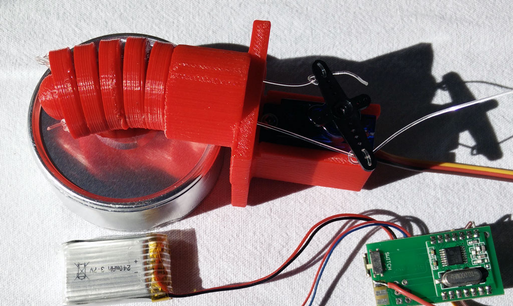 So far we have used vibration motors for our sex toys. Vibration motors are cheap, powerful, easy to control and robust actuators. That’s why they are part of most sex toys. But what about moving or touching objects. Obviously we need some mechanics, maybe joints and gears? Or is there a simple option? A skeleton?
I realized the idea for using some type of skeleton for moving a dildo when I saw the video of a naked Pleo – one of the best artificial life forms ever.

On www.thingiverse.com you will find more inspiration for using a skeleton to move something. The design is very simple.
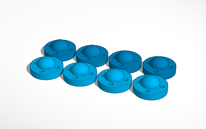
The skeleton is composed of a number of vortexes. The holes are for connecting all vortexes and a servo with a nylon wire or similar.
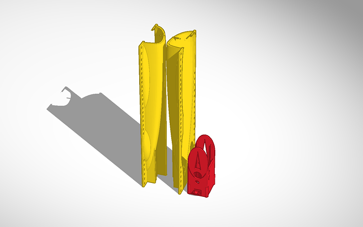
In addition we need a handle where the vortexes are fastened to. There is also space for a servo. Then use a nylon wire to connect the vortexes with the servo. You can drive the servo with a Arduino development board or you use the body interaction development board as described here.

The servo should turn only 15-30 degree or so. If you use the body interaction development board please copy the following code and upload the code to the board.
#include <TinyServo.h>
// servo control with the body interaction development board using the TinyServo library
// -- adaption of the demo script by
// tylernt@gmail.com's ATTiny Hardware Timer Assisted Servo Library v1.0 20-Nov-13
// http://forum.arduino.cc/index.php?action=dlattach;topic=198337.0;attach=71790
const byte SERVOS = 1; // number of servos is 1
const byte servoPin[SERVOS] = { 7 }; // servo is connected to PA1 which is pin 7
#define SERVO 0 // our servo is given the name &quot;SERVO&quot;
void setup() {
setupServos();
}
void loop() {
moveServo(SERVO, 0); // move servo to 0°
delay(1000);
moveServo(SERVO, 30); // move servo to 30°
delay(2000);
}
In addition we need a wrapping for the skeleton. This can be made using these two forms (download STL files).

Use flexible silicone and poor it in the form. The thickness of the wrapping is a bit too large – it rather hinders the skeleton in its movements. But it works!

Now we can put everything together.
Download on Thingiverse: http://www.thingiverse.com/thing:1736282
Tinker with Tinkercad!
Form: https://tinkercad.com/things/e8yscABu9Al
Skeleton: https://tinkercad.com/things/dfbMQsE4Mtl
Servo handle: https://tinkercad.com/things/5EHHrqM5sqC
YouTube: https://youtu.be/F1b8bGbuSHw
Exploring the internet of (sex) things 1
The internet of things – or short IOT – is getting popular. IOT is a network of physical things like vehicles, buildings, but also everyday objects like lamps, refrigerators. IOT allows objects to be sensed and controlled remotely across the Internet. As a result the physical world will be integrated into the internet and computer systems.
Popular examples are home axiomatization or collection of environmental data. Even sex toy industry use the internet to connect sex toy users which are far away of each other (like the OhMiBod blueMotion). The vision of remote sex driven by technology is also known as Teledildonics. Unfortunately I didn’t pay much attention to this movement which goes back to 1975. body interaction focused more on wireless connected sex toys for users having sex together and want to integrate his and her’s sex toy. You will find a lot of information at Kyle Machulis site Metafetish. Also have a look at the annual conference Arse Elektronika which focus on the intersection of technology and sex.
In this blog I have already shown how to connect the body interaction development board to the internet. Now I will present some first steps into IOT. I will use the NodeMCU development board which is based on the popular ESP8266 System on a chip. The ESP is a wi-fi enabled microcontroller where you can connect sensors and actuators. It can connect to your wi-fi access point and home and it can be an access point itself and host eg. an internet server.
In my explorations I will try to find out if a IOT sex toy is useful for DIY sex toy community.
In this blog post we will use the ESP8266 as a wi-fi server. The server will connect to your wi-fi access point at home.
The series has 4 parts:
part 1: Exploring the internet of (sex) things
part 4: Building a sex toy dashboard with Node-RED
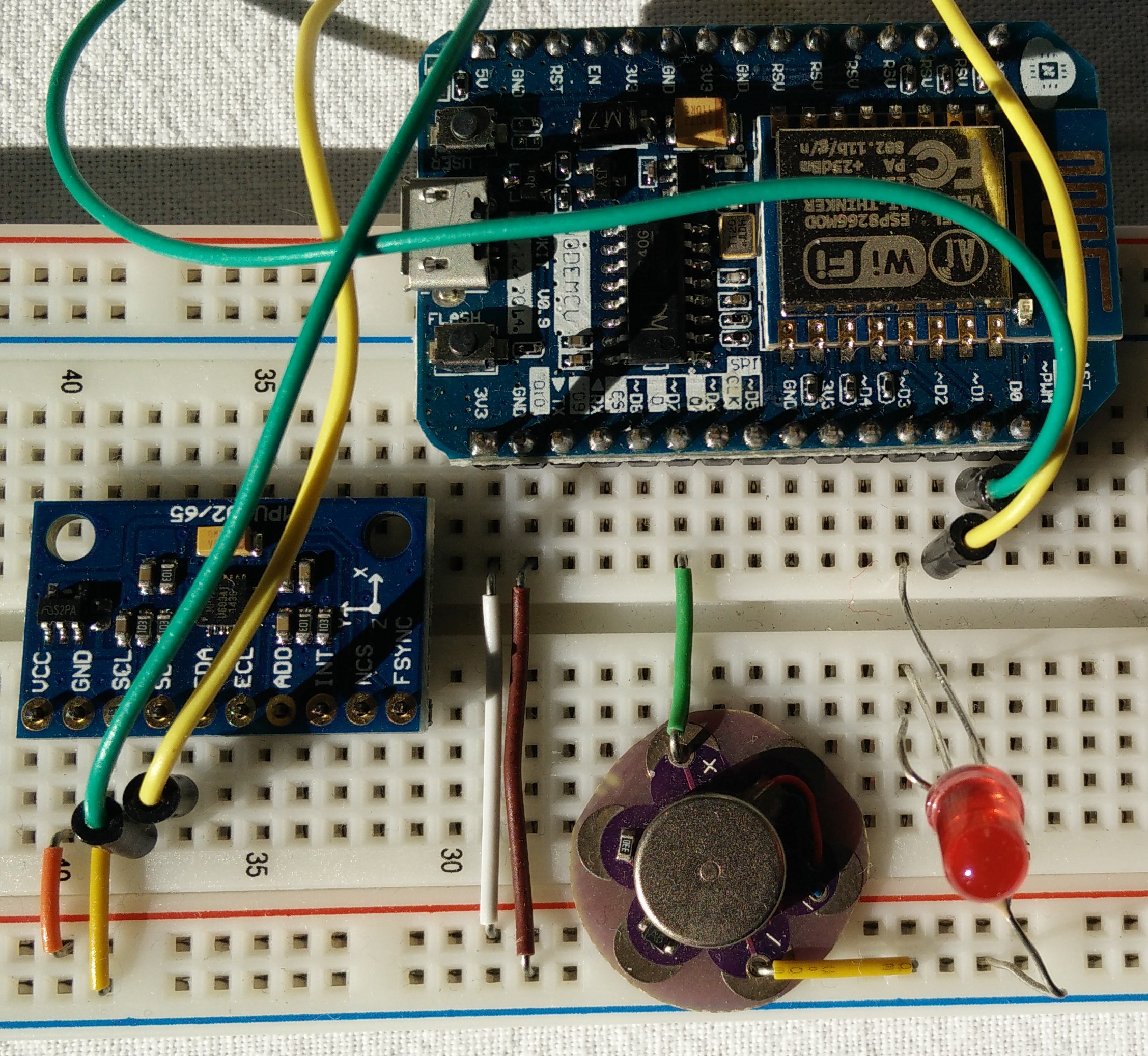
Building a bread board prototype
Material needed
- bread board, wires
- Node MCU or similar
- small vibration motor (or LED), eg the Lilipad vibration motor
- optional: accelerometer MPU9265
- optional: another LED and a resistor
WIre MPU9265
 Connect
- SCL (on MPU9265) and D1 (on NodeMCU),
- SDA and D2,
- VCC and 3V3
- GND and GND
Wire vibration motor
Connect
- D7 (node MCU) with vibration motor (+) and
- GND (NodeMCU) and (-)
Wire LED
Connect:
- D3 (NodeMCU) and LED (long end)
- LED (short end) and resistor
- resistor and GND (NodeMCU)
Using the Arduino IDE
NodeMCU and all other ESP8266 boards are not supported by Arduino. But you can use the Arduino board manager to add other development boards. This short Tutorial explains the necessary steps: http://www.instructables.com/id/Quick-Start-to-Nodemcu-ESP8266-on-Arduino-IDE/
Connect the NodeMCU to your access point (WLAN router)
Upload script to NodeMCU
Copy the code below to the Arduino IDE or download and unzip this Arduino “.ino” file.
Within the sketch you have to change the constants SSID and password. Use the same SSID as you would do to connect your smart phone or computer to the internet.
Select your NodeMCU and the port. Connect your computer and the NodeMCU with USB wire. Upload the script to NodeMCU
#include <ESP8266WiFi.h>
#include <Wire.h>

#define MPU9250_ADDRESS 0x68
#define MAG_ADDRESS 0x0C

#define GYRO_FULL_SCALE_250_DPS 0x00
#define GYRO_FULL_SCALE_500_DPS 0x08
#define GYRO_FULL_SCALE_1000_DPS 0x10
#define GYRO_FULL_SCALE_2000_DPS 0x18

#define ACC_FULL_SCALE_2_G 0x00
#define ACC_FULL_SCALE_4_G 0x08
#define ACC_FULL_SCALE_8_G 0x10
#define ACC_FULL_SCALE_16_G 0x18

const char* ssid = "????"; // Enter the name of your Access point
const char* password = "????"; //Enter the password SSID
int ledPin = 0; // NodeMCU pad D3 = GPI0
int motorPin= 13; // NodeMCU pad D7 = GPIO 13
double sinusValue=0;

// define constants for four different vibration modes
const int off_mode=0;
const int max_mode =1;
const int sinus_mode =2;
const int motion_mode =3;

int motor_mode =off_mode;

WiFiServer server(80);

 // This function read Nbytes bytes from I2C device at address Address.
// Put read bytes starting at register Register in the Data array.
void I2Cread(uint8_t Address, uint8_t Register, uint8_t Nbytes, uint8_t* Data)
{
 // Set register address
 Wire.beginTransmission(Address);
 Wire.write(Register);
 Wire.endTransmission();

 // Read Nbytes
 Wire.requestFrom(Address, Nbytes);
 uint8_t index=0;
 while (Wire.available())
 Data[index++]=Wire.read();
}

// Write a byte (Data) in device (Address) at register (Register)
void I2CwriteByte(uint8_t Address, uint8_t Register, uint8_t Data)
{
 // Set register address
 Wire.beginTransmission(Address);
 Wire.write(Register);
 Wire.write(Data);
 Wire.endTransmission();
}

void setup() {

 Wire.begin();
 // NodeMCU D1 = GPIO5 connected to MCU9265 SCL
 // NodeMCU D2 = GPIO4 connected to MCU9265 SDA
 Wire.pins(5,4);
 Serial.begin(115200);

 // Configure gyroscope range
 I2CwriteByte(MPU9250_ADDRESS,27,GYRO_FULL_SCALE_2000_DPS);
 // Configure accelerometers range
 I2CwriteByte(MPU9250_ADDRESS,28,ACC_FULL_SCALE_16_G);
 // Set by pass mode for the magnetometers
 I2CwriteByte(MPU9250_ADDRESS,0x37,0x02);

 // Request first magnetometer single measurement
 I2CwriteByte(MAG_ADDRESS,0x0A,0x01);

 Serial.begin(115200);
 delay(10);

 pinMode(ledPin, OUTPUT);
 digitalWrite(ledPin, LOW);

 pinMode(motorPin, OUTPUT);
 analogWrite(motorPin, 0);

 // Connect to WiFi network
 Serial.println();
 Serial.println();
 Serial.print("Connecting to ");
 Serial.println(ssid);

 WiFi.begin(ssid, password);

 while (WiFi.status() != WL_CONNECTED) {
 delay(500);
 Serial.print(".");
 }
 Serial.println("");
 Serial.println("WiFi connected");

 // Start the server
 server.begin();
 Serial.println("Server started");

 // Print the IP address
 Serial.print("Use this URL to connect: ");
 Serial.print("http://");
 Serial.print(WiFi.localIP());
 Serial.println("/");

}

int16_t ax,ay,az,ax1,ay1,az1,gx,gy,gz,gx1,gy1,gz1;
int valueMotor; //vibrator motor speed 0-1023

void loop() {

 // Read accelerometer and gyroscope
 uint8_t Buf[14];
 I2Cread(MPU9250_ADDRESS,0x3B,14,Buf);

 // Create 16 bits values from 8 bits data

 // Accelerometer
 ax=-(Buf[0]<<8 | Buf[1]);
 ay=-(Buf[2]<<8 | Buf[3]);
 az=Buf[4]<<8 | Buf[5];

 // Gyroscope
 gx=-(Buf[8]<<8 | Buf[9]);
 gy=-(Buf[10]<<8 | Buf[11]);
 gz=Buf[12]<<8 | Buf[13];  // when in "motion_mode" the vibration motor
//is controlled by motion
if (motor_mode==motion_mode) {
  int v = 0;
  //calculate motion vector
  v=sqrt(pow(ax-ax1,2)+pow(ay-ay1,2)+pow(az-az1,2));

  // adjust vibration motor speed
  // if motion vector > 5000 raise speed by 25
  // otherwise lower speed by 10
  // adjust these constants to your needs
  if (v > 5000) {valueMotor=valueMotor+25;} else {valueMotor=valueMotor-10;}

  //values must be above 500 otherwise the motor is off
  if (valueMotor<500) {valueMotor=500;}
  // values higher than 1023 are not supported
  if (valueMotor>1023) {valueMotor=1023;}
  analogWrite(motorPin, valueMotor); // set motor speed

  Serial.print("v: ");
  Serial.print(v);
  Serial.print(", valueMotor: ");
  Serial.println(valueMotor);
  delay(200);

  // save values
  ax1=ax;
  ay1=ay;
  az1=az;
  gx1=gx;
  gy1=gy;
  gz1=gz;
 }

 // change vibration motor speed according to a sinus curve
 if (motor_mode==sinus_mode) {
 sinusValue=sinusValue+.01;
 delay(20);
 int sin_tmp = ((sin(sinusValue)+1)*.5*(1023-500))+500;
 Serial.println(sin_tmp);
 analogWrite(motorPin, sin_tmp);
 valueMotor=sin_tmp;
 }

 // Check if a client has connected
 WiFiClient client = server.available();
 if (!client) {
 return;
 }

 // Wait until the client sends some data
 Serial.println("new client");
 while(!client.available()){
 delay(1);
 }

 // Read the first line of the request
 String request = client.readStringUntil('\r');
 Serial.println(request);
 client.flush();

 // Match the request

 int valueLED = LOW;
 if (request.indexOf("/LED=ON") != -1) {
 digitalWrite(ledPin, HIGH);
 valueLED = HIGH;
 }
 if (request.indexOf("/LED=OFF") != -1) {
 digitalWrite(ledPin, LOW);
 valueLED = LOW;
 }

 if (request.indexOf("/MOTOR=MAX") != -1) {
 analogWrite(motorPin, 1023);
 valueMotor = 1023;
 motor_mode=max_mode;
 }
 if (request.indexOf("/MOTOR=OFF") != -1) {
 analogWrite(motorPin, 0);
 valueMotor = 0;
 motor_mode=off_mode;
 }

 if (request.indexOf("/MOTOR=SINUS") != -1) {
 motor_mode=sinus_mode;
 }

 if (request.indexOf("/MOTOR=MOTION") != -1) {
 motor_mode=motion_mode;
 valueMotor=600;
 }

 // Return the response
 client.println("HTTP/1.1 200 OK");
 client.println("Content-Type: text/html");
 client.println(""); // do not forget this one
 client.println("<!DOCTYPE HTML>");
 client.println("<html>");

 client.print("Led pin is now: ");

 if(valueLED == HIGH) {
 client.print("On");
 } else {
 client.print("Off");
 }

 client.print("Motor pin is now: ");
 client.print(valueMotor);

 client.println("");
 client.println("<a href=\"/LED=ON\"\"><button>Turn On </button></a>");
 client.println("<a href=\"/LED=OFF\"\"><button>Turn Off </button></a>");
 client.println("<a href=\"/MOTOR=MAX\"\"><button>Motor Max </button></a>");
 client.println("<a href=\"/MOTOR=OFF\"\"><button>Motor Off </button></a>");
 client.println("<a href=\"/MOTOR=SINUS\"\"><button>Motor sinus curve </button></a>");
 client.println("<a href=\"/MOTOR=MOTION\"\"><button>Motor motion controlled </button></a>");
 client.println("</html>");

 delay(1);
 Serial.println("Client disonnected");
 Serial.println("");

}
Controlling the vibrator prototype
After uploading the script above, open the serial monitor. After some time the NodeMCU will report “wifi connected”.
 Now start a browser. Use the URL which the NodeMCU reported eg. http://192.168.1.12/
If your smart phone is connected to the same Access point as your computer is, you can use your smart phone to control the prototype, too.
You can turn the LED on or off by pressing the “Turn On” and “Turn Off” buttons.
For controlling the motor you have 4 options
- motor on
- motor off
- sinus curve (the motor will speed up and slow down according to a sinus curve)
- motion controlled (more motion -> motor speeds up)
Summary
To build a vibrator prototype based on the ESP8266 MCU is very easy. You can use your Arduino IDE to upload scripts to the prototype. Then you can control the vibration motor through a browser. If you don’t want to use these external control options the vibrator prototype can be controlled by motion similar to the body interaction vibrator development board.
In this blog post series we will explore other interesting features of the ESP8266:
- the ESP8266 as an access point (no need for private or public access points)
- over the air (OTA) uploading of sketches (wireless – no USB connector needed)
- MQTT protocol & server
- Node-RED (visual IOT programming)
- review of development boards for building IOT vibrators
New vibrator design “fusion”
 bodyinteraction designed a lot of vibrating toys, some are usable as massage devices, some are explicit sex toys (vibrator ring, balls), some are experimental (collar). Everyone is motion controlled. If you have more than one they will influence each other remotely, eg. a vibrator and a vibrator ring.

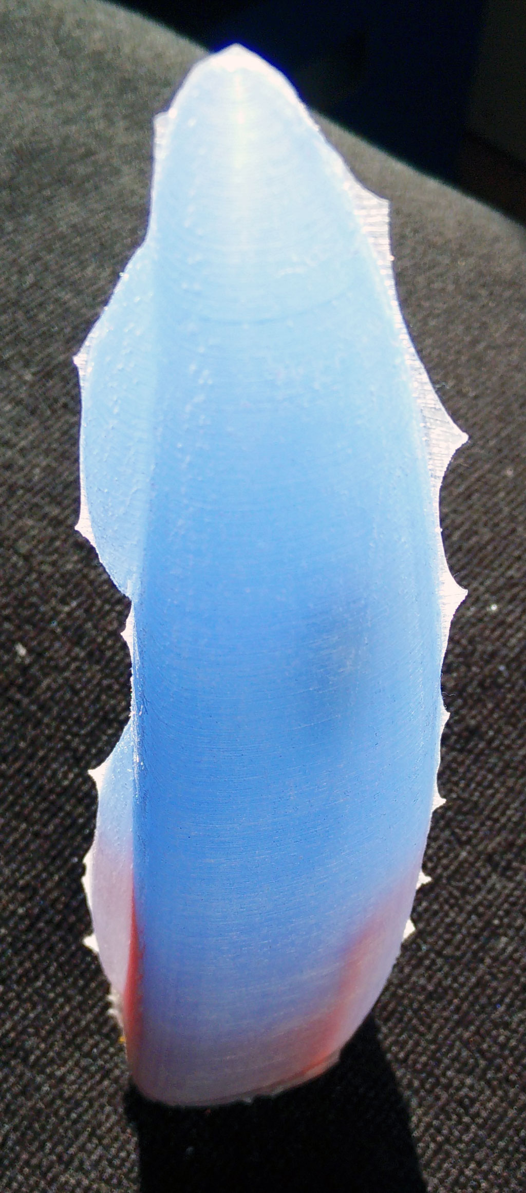
But a device like a classic big vibrator is still missing. So we designed the “fusion” which is approx 19cm long and up to 4+cm in diameter. It is called fusion as the case is made of silicone and 3d printed material (ABS).

We have put the body interaction vibrator development board, motor and battery in a silicone form. There is an on/off switch – so when you travel the vibrator doesn’t wake up when it is moved. And you can charge the battery with a USB micro connector. There is a spacious inlay for the electronics, so it will be easy to get it done.
Pros:
- easy to charge the battery via USB
- on/off switch
- hard handle
- flexible upper part
- large (if you like this)
- ISP interface (“hacker port”) accessible
Cons:
- only the silicone part of the form can be put under water for cleaning
What do you need?
- 200 ml silicone with high shore A rate, eg. shore A 45 from silikonfabrik.de
- optional: special colour for silicone molding
- 3d print of the molding form, inlay and closure
- tinker wire
- body interaction vibrator development board with LiPo and motor (or similar Arduino boards)
- bin for preparing the silicone, something to stir the silicone
How much is it?
- Board, battery, motor: 30$ (buy at Tindie)
- Silicone: 10$
- 3d Prints: less than 5$
Step by step instructions
Step 1: Print out the inlay, the form and the enclosure
Download as zip-file: Fusion
Download at Thingiverse: http://www.thingiverse.com/thing:1505539
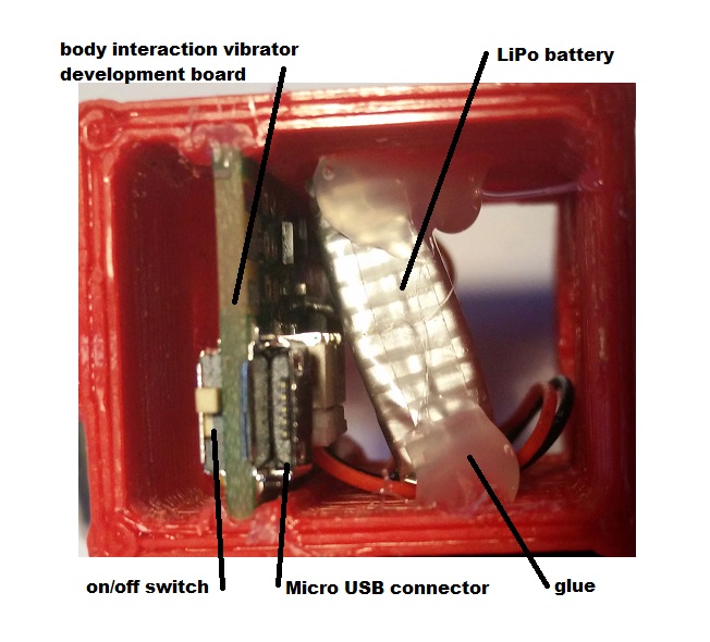
Step 2: Prepare the inlay: Insert the body interaction board and the LiPo battery
The body interaction vibrator development board is inserted into the provided rails. It it doesn’t fit in use a file to remove printing artefacts. Use some glue to fix the board. Then insert the battery and fix it.
Important: The Micro USB connector must be above the upper part of the inlay.
Step 3: fix the wires of the vibration motor
The vibration motor will hang down from the inlay as the inlay will be put in the form upside down. You can influence the position of the motor by shortening the wire or fixing the wire to e.g. to the battery. In this case the wire of the motor was threaded between battery and board. Therefore the motor will be in the middle of the vibrator.

 in the center there is the overmolded vibration motor
Step 5: Prepare the form
Use some tinker wire to “press” both parts of the form tight together. Use some wax to fix little holes in the form where the printer failed. (These are the white spots)

Step 6: Insert inlay into the form
There must be some space between inlay and form for the silicone.
Remark: The two wedge like forms at both sides of the inlay help to hold the inlay. The wedge can be removed after molding.
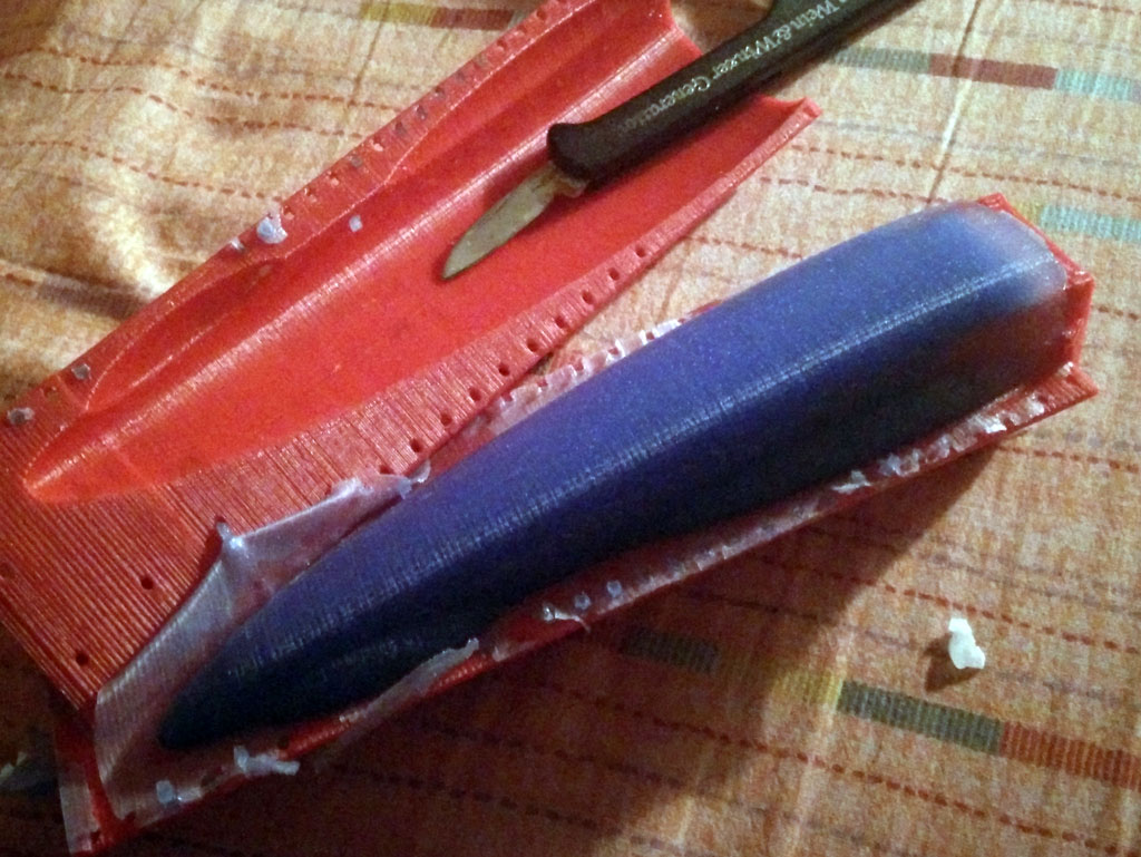
Step 7: Cast the silicone
Prepare the silicone as the producer recommends. It takes some time to pour the large amount of silicone into the narrow form. The silicone we use must be used within 10 minutes. So start at once after preparing the silicone.
Important: The USB micro connector, the switch and the ISP connector shouldn’t be dashed with silicone. If this happens remove the silicone. Maybe some silicone will remain behind. This can be removed later when the silicone is solid.
The battery is covered with silicone, the USB connecor and switch are not.
Step 8: Remove the form
Remove the tinker wire. Remove overhanging part of the silicone. Carefully tear both parts of the form away. You can use a knife, but be careful not to “hurt” the vibrator. Remove overhanging silicone at the vibrator. Also remove the two wedge like forms at both sides of the inlay.
Step 9: Install the closure
Now you can put the closure on the inlay. Fix the closure with glue. (Be careful! The USB connector is not very strong.) 


Tinker, share and download from Tinkercad:
form and inlay: https://tinkercad.com/things/b8nQxRn4XWl
closure: https://tinkercad.com/things/dhgtgeaYG0B
Download as zip-file: Fusion
Download at Thingiverse:
http://www.thingiverse.com/thing:1505539
