
in the second part of this tutorial we have seen how to use the MQTT protocol to send data across the internet. In the third part we show how to add additional functionalities to our sex toys.
The series has 4 parts:
part 1: Exploring the internet of (sex) things
part 4: Building a sex toy dashboard with Node-RED
We want to enable sex toys to communicate and to connect to social media. Although there are a lot of solutions from the Internet of Things (IoT) community Node-RED is outstanding as you could connect devices without or with little knowledge of programming languages: “Node–RED is a visual tool for wiring together hardware devices, APIs and online services – for wiring the Internet of Things.” (Wikipedia). There are standard building blocks (called nodes) which are categorized as input, output, function and social nodes. You can select nodes and wire them to create a flow. A typical flow would look like that: input node- function node- output node. If you want to know more you can should have a look at this very good tutorial: http://noderedguide.com/
In this part of the tutorial we will receive and display data from the sex toy. And we want to send control commands to the sex toy. This can be achieved with a few flows in Node-RED:
Installation of Node-RED:
- First you have to install “node.js”. Follow the instructions here.
- Now follow the node-red installation instruction.
For Windows: Press the Windows button. Type in “CMD”. Windows should suggest the command shell app. Now RIGHT-click on the command shell app and select “open as administrator”. In the new command shell window type innpm install -g --unsafe-perm node-red - Change to the Node-RED directory and start Node-RED by the command “node red” or “node red.js”
- Go to your browser and open http://127.0.0.1:1880/
If you don’t want to make a local installation of Node-RED the online service FRED (https://fred.sensetecnic.com/) offers a good alternative. FRED comes with additional nodes with extra functionalities.
Let’s start with a first flow. We want to control the LED and the motor of our IoT sex toys. Therefore we need two nodes: The input node “INJECT” and the output node “MQTT”. Select both nodes and drag them into the flow window in the middle. Wire both nodes. Then open the Inject-node (just double-click the node). Change the payload to type “string” and type in the command for switching the LED. This command is taken from the second part of the tutorial:
{messageType : "execute", actuator : "LED", actuatorValue : 1 }
In addition you have to enter the topic that will be used for the MQTT message. It is “BIinTopic” – the “in” refers to the sex toy. Select a name like “set LED on”:
Then edit the MQTT node. The name of the MQTT server must be entered. Leave the Topic field empty and the MQTT node will use the topic from the predecessor node INJECT.
 Now press the deploy button. You should see the message “successful deployed”.
Now you can press one of the INJECT node button (the button is on the left side of the node) and the LED of the sex toy should go on.
You can use the JSON commands from part 2 of the tutorial and make an INJECT node for each command. With just 5 flows you can control all functions of the vibrator from everywhere. Instead of the INJECT node you could use an Email or Twitter node (instead of the INJECT node) to control the sex toy eg by Email.
There are no file open or save menus in Node-RED. Instead the visual flow can be imported and exported using a simple text file. If you want to import the flow above download and unzip this text file. Select Import -> from clipboard and copy the text from the file to the clipboard. If you want to save the flow, select Export -> from clipboard and copy the text of the clipboard in a new text file.
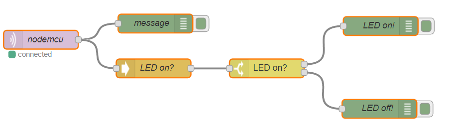
Now let’s receive messages from the vibrator and parse them. You need a MQTT input node, a JSON function node, a SWITCH node and two DEBUG output node.
We will show how to retrieve the status of the LED. When the LED is on the JSON file includes: “LEDstatus: 1”. Otherwise the JSON file includes: “LEDstatus: 0”.
Edit the MQTT input node and enter the URL of the Mosquitto server and the topic “BIoutTopic”.

Then add a DEBUG node and select “complete msg”. Wire MQTT and DEBUG node. This node will display the MQTT message in the debug slider (on the rights side). This is only for debugging – you will see if the message from the vibrator comes in (or not).
Now add a JSON function node and connect the MQTT node with the JSON node. The JSON function node will parse the text string which was sent via MQTT and transforms it to a JSON object.
Now select a SWITCH node. As property enter “payload.LEDstatus”. The switch node branches the flow according to LED status which was reported in the JSON file. Now we can test, if the LEDstatus is 0 or 1. For each comparison a line will be added.
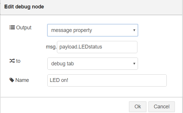
Finally make two DEBUG output nodes and wire them with the SWITCH node. Complete the “msg” by adding “payload.LEDstatus”. If the flow reaches the DEBUG nodes you will see a message in the debug slider on the right.
Now you are ready and can press the deploy button. It should look like that:
Again, the visual flow can be imported. If you want to import the flow above download and unzip this text file. Select Import -> from clipboard and copy the text from the file to the clipboard.
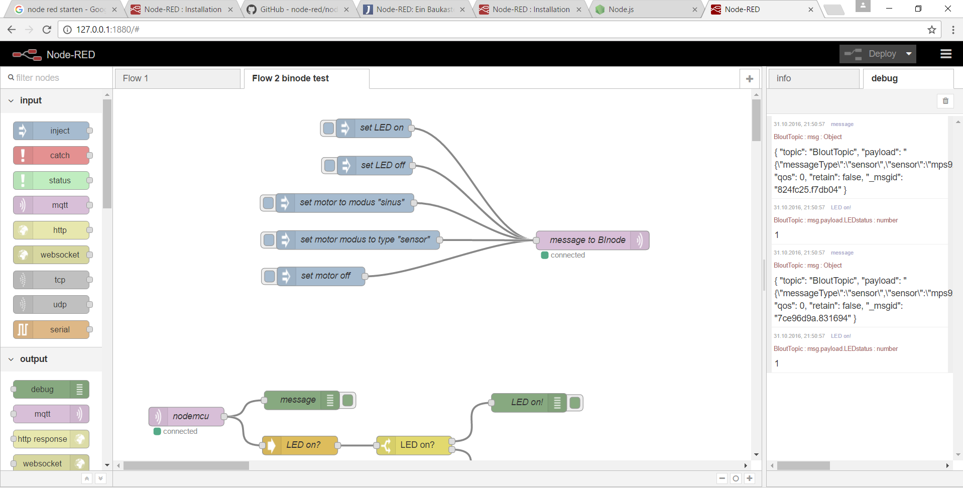
Let us test the flow. You have to set the LED on. Press the “turn on” button in your browser as explained in part 2.
Now have a look at the “debug” slider where you should see the result of the action. The first entry is the JSON file which was received. It is displayed by the DEBUG node “message”. In the second entry the DEBUG node (wired with the SWITCH node) displays 1 which means the LED is on.
With Node-RED you can add a SQL database to store all data, you can connect to social media and especially you can connect MULTIPLE sex toys and let them interact. Read the excellent guides for parsing JSON files and MQTT:
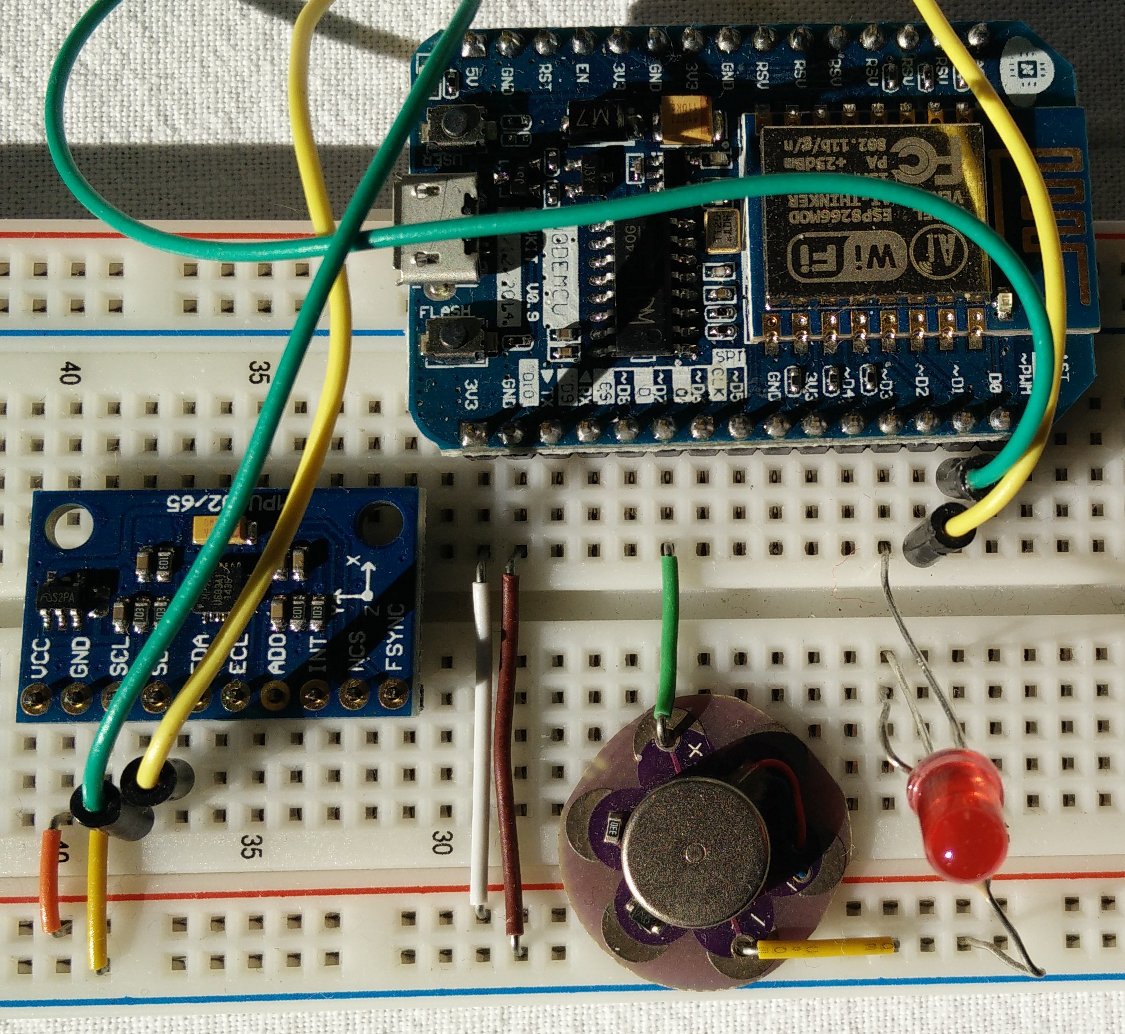
What we have achieved: In part 1 we have developed a wifi-enabled sex toy prototype based on the ESP8266. The toy was controlled through a web browser on a local smart phone / laptop. Local refers to the access point. Both the local smart phone / laptop and the ESP8266 must have access to the same access point (eg your router at home.)
In part 2 we opened our connections to the internet. With the fast MQTT protocol we are able to send and receive messages from anywhere. For data transmission we use the JSON file format. We have sketched a protocol for sending data, commands and messages between sex toys and users.
In this part we introduced Node-RED a visual programming tool for the Internet of Things. With this tool we are able to connect sex toys at different locations, to store sensor data and to get social.
In the fourth part of the tutorial we will introduce User Interfaces to create a sex toy dashboard.

One thought on “Internet of (sex) things – part 3: Node-RED”