The internet of things – or short IOT – is getting popular. IOT is a network of physical things like vehicles, buildings, but also everyday objects like lamps, refrigerators. IOT allows objects to be sensed and controlled remotely across the Internet. As a result the physical world will be integrated into the internet and computer systems.
Popular examples are home axiomatization or collection of environmental data. Even sex toy industry use the internet to connect sex toy users which are far away of each other (like the OhMiBod blueMotion). The vision of remote sex driven by technology is also known as Teledildonics. Unfortunately I didn’t pay much attention to this movement which goes back to 1975. body interaction focused more on wireless connected sex toys for users having sex together and want to integrate his and her’s sex toy. You will find a lot of information at Kyle Machulis site Metafetish. Also have a look at the annual conference Arse Elektronika which focus on the intersection of technology and sex.
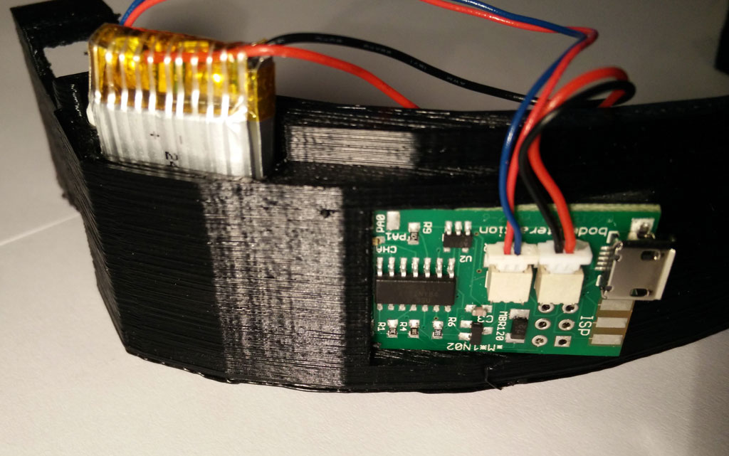
In this blog I have already shown how to connect the body interaction development board to the internet. Now I will present some first steps into IOT. I will use the NodeMCU development board which is based on the popular ESP8266 System on a chip. The ESP is a wi-fi enabled microcontroller where you can connect sensors and actuators. It can connect to your wi-fi access point and home and it can be an access point itself and host eg. an internet server.
In my explorations I will try to find out if a IOT sex toy is useful for DIY sex toy community.
In this blog post we will use the ESP8266 as a wi-fi server. The server will connect to your wi-fi access point at home.
The series has 4 parts:
part 1: Exploring the internet of (sex) things
part 2: MQTT messages
part 3: Node-RED
part 4: Building a sex toy dashboard with Node-RED
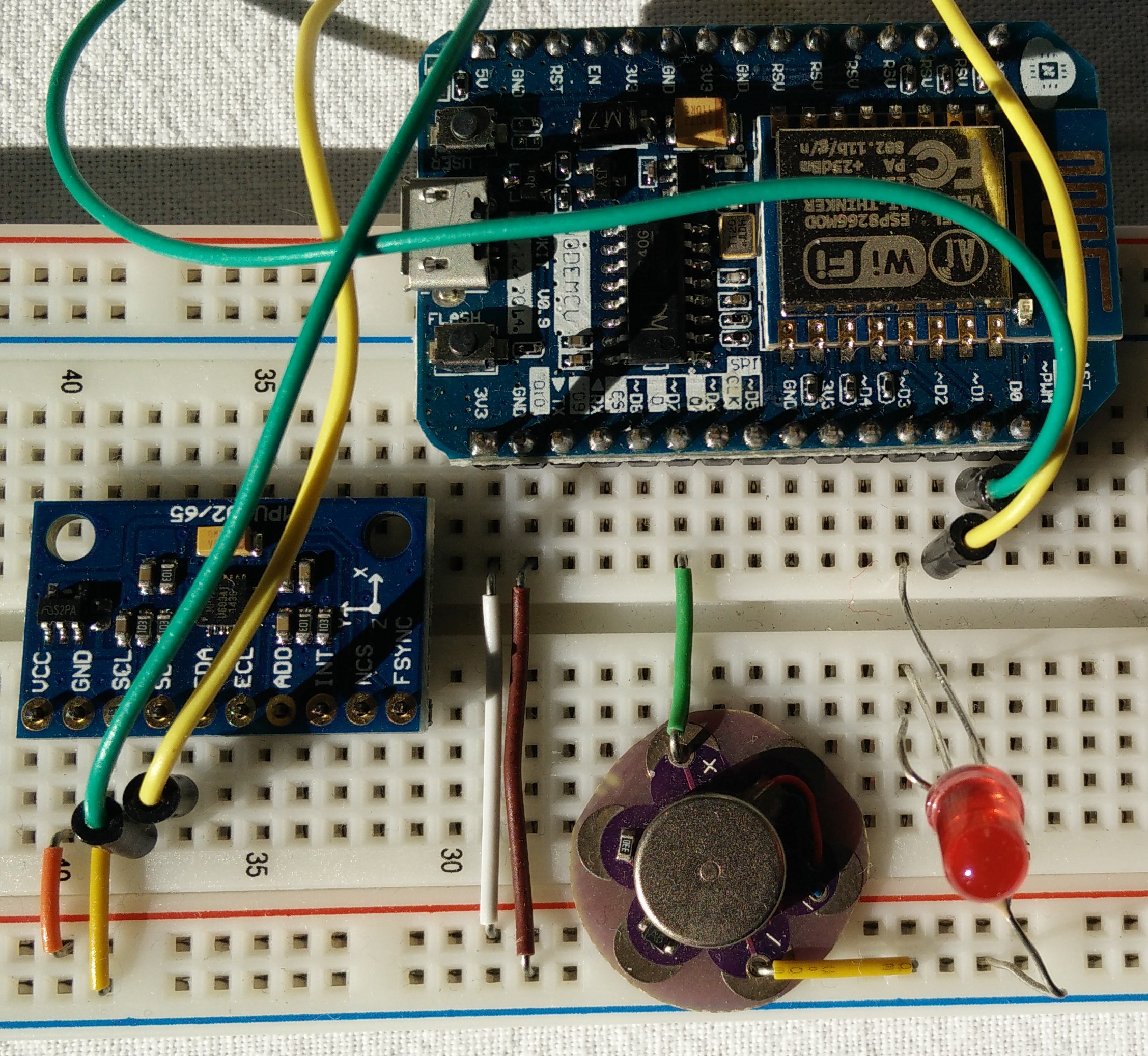
Building a bread board prototype

Material needed
- bread board, wires
- Node MCU or similar
- small vibration motor (or LED), eg the Lilipad vibration motor
- optional: accelerometer MPU9265
- optional: another LED and a resistor
WIre MPU9265
 Connect
- SCL (on MPU9265) and D1 (on NodeMCU),
- SDA and D2,
- VCC and 3V3
- GND and GND
Wire vibration motor
Connect
- D7 (node MCU) with vibration motor (+) and
- GND (NodeMCU) and (-)
Wire LED
Connect:
- D3 (NodeMCU) and LED (long end)
- LED (short end) and resistor
- resistor and GND (NodeMCU)
Using the Arduino IDE
NodeMCU and all other ESP8266 boards are not supported by Arduino. But you can use the Arduino board manager to add other development boards. This short Tutorial explains the necessary steps: http://www.instructables.com/id/Quick-Start-to-Nodemcu-ESP8266-on-Arduino-IDE/
Connect the NodeMCU to your access point (WLAN router)
Upload script to NodeMCU
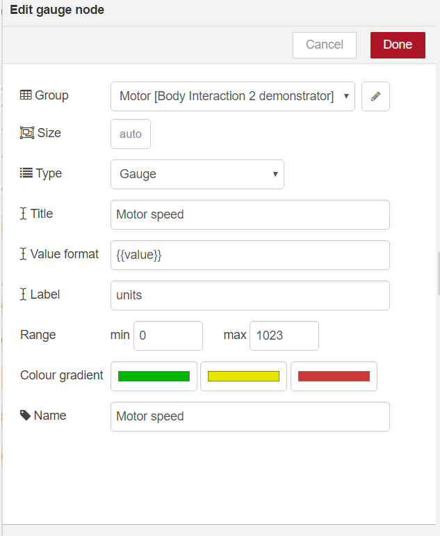
Copy the code below to the Arduino IDE or download and unzip this Arduino “.ino” file.
Within the sketch you have to change the constants SSID and password. Use the same SSID as you would do to connect your smart phone or computer to the internet.
Select your NodeMCU and the port. Connect your computer and the NodeMCU with USB wire. Upload the script to NodeMCU
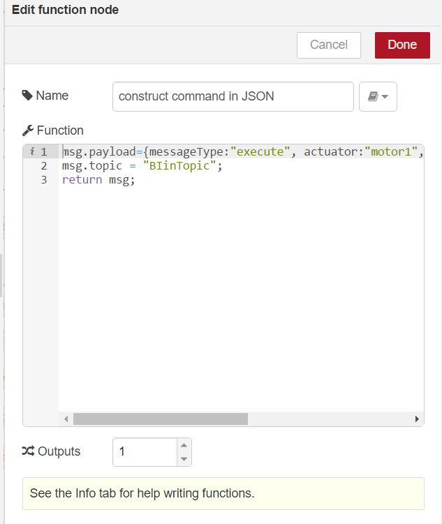
#include <ESP8266WiFi.h>
#include <Wire.h>
#define MPU9250_ADDRESS 0x68
#define MAG_ADDRESS 0x0C
#define GYRO_FULL_SCALE_250_DPS 0x00
#define GYRO_FULL_SCALE_500_DPS 0x08
#define GYRO_FULL_SCALE_1000_DPS 0x10
#define GYRO_FULL_SCALE_2000_DPS 0x18
#define ACC_FULL_SCALE_2_G 0x00
#define ACC_FULL_SCALE_4_G 0x08
#define ACC_FULL_SCALE_8_G 0x10
#define ACC_FULL_SCALE_16_G 0x18
const char* ssid = "????"; // Enter the name of your Access point
const char* password = "????"; //Enter the password SSID
int ledPin = 0; // NodeMCU pad D3 = GPI0
int motorPin= 13; // NodeMCU pad D7 = GPIO 13
double sinusValue=0;
// define constants for four different vibration modes
const int off_mode=0;
const int max_mode =1;
const int sinus_mode =2;
const int motion_mode =3;
int motor_mode =off_mode;
WiFiServer server(80);
// This function read Nbytes bytes from I2C device at address Address.
// Put read bytes starting at register Register in the Data array.
void I2Cread(uint8_t Address, uint8_t Register, uint8_t Nbytes, uint8_t* Data)
{
// Set register address
Wire.beginTransmission(Address);
Wire.write(Register);
Wire.endTransmission();
// Read Nbytes
Wire.requestFrom(Address, Nbytes);
uint8_t index=0;
while (Wire.available())
Data[index++]=Wire.read();
}
// Write a byte (Data) in device (Address) at register (Register)
void I2CwriteByte(uint8_t Address, uint8_t Register, uint8_t Data)
{
// Set register address
Wire.beginTransmission(Address);
Wire.write(Register);
Wire.write(Data);
Wire.endTransmission();
}
void setup() {
Wire.begin();
// NodeMCU D1 = GPIO5 connected to MCU9265 SCL
// NodeMCU D2 = GPIO4 connected to MCU9265 SDA
Wire.pins(5,4);
Serial.begin(115200);
// Configure gyroscope range
I2CwriteByte(MPU9250_ADDRESS,27,GYRO_FULL_SCALE_2000_DPS);
// Configure accelerometers range
I2CwriteByte(MPU9250_ADDRESS,28,ACC_FULL_SCALE_16_G);
// Set by pass mode for the magnetometers
I2CwriteByte(MPU9250_ADDRESS,0x37,0x02);
// Request first magnetometer single measurement
I2CwriteByte(MAG_ADDRESS,0x0A,0x01);
Serial.begin(115200);
delay(10);
pinMode(ledPin, OUTPUT);
digitalWrite(ledPin, LOW);
pinMode(motorPin, OUTPUT);
analogWrite(motorPin, 0);
// Connect to WiFi network
Serial.println();
Serial.println();
Serial.print("Connecting to ");
Serial.println(ssid);
WiFi.begin(ssid, password);
while (WiFi.status() != WL_CONNECTED) {
delay(500);
Serial.print(".");
}
Serial.println("");
Serial.println("WiFi connected");
// Start the server
server.begin();
Serial.println("Server started");
// Print the IP address
Serial.print("Use this URL to connect: ");
Serial.print("http://");
Serial.print(WiFi.localIP());
Serial.println("/");
}
int16_t ax,ay,az,ax1,ay1,az1,gx,gy,gz,gx1,gy1,gz1;
int valueMotor; //vibrator motor speed 0-1023
void loop() {
// Read accelerometer and gyroscope
uint8_t Buf[14];
I2Cread(MPU9250_ADDRESS,0x3B,14,Buf);
// Create 16 bits values from 8 bits data
// Accelerometer
ax=-(Buf[0]<<8 | Buf[1]);
ay=-(Buf[2]<<8 | Buf[3]);
az=Buf[4]<<8 | Buf[5];
// Gyroscope
gx=-(Buf[8]<<8 | Buf[9]);
gy=-(Buf[10]<<8 | Buf[11]);
gz=Buf[12]<<8 | Buf[13]; // when in "motion_mode" the vibration motor
//is controlled by motion
if (motor_mode==motion_mode) {
int v = 0;
//calculate motion vector
v=sqrt(pow(ax-ax1,2)+pow(ay-ay1,2)+pow(az-az1,2));
// adjust vibration motor speed
// if motion vector > 5000 raise speed by 25
// otherwise lower speed by 10
// adjust these constants to your needs
if (v > 5000) {valueMotor=valueMotor+25;} else {valueMotor=valueMotor-10;}
//values must be above 500 otherwise the motor is off
if (valueMotor<500) {valueMotor=500;}
// values higher than 1023 are not supported
if (valueMotor>1023) {valueMotor=1023;}
analogWrite(motorPin, valueMotor); // set motor speed
Serial.print("v: ");
Serial.print(v);
Serial.print(", valueMotor: ");
Serial.println(valueMotor);
delay(200);
// save values
ax1=ax;
ay1=ay;
az1=az;
gx1=gx;
gy1=gy;
gz1=gz;
}
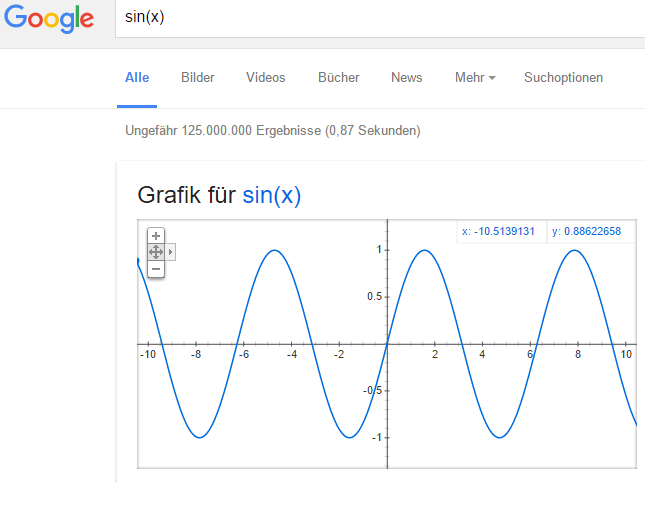
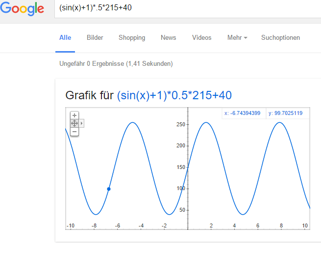
// change vibration motor speed according to a sinus curve
if (motor_mode==sinus_mode) {
sinusValue=sinusValue+.01;
delay(20);
int sin_tmp = ((sin(sinusValue)+1)*.5*(1023-500))+500;
Serial.println(sin_tmp);
analogWrite(motorPin, sin_tmp);
valueMotor=sin_tmp;
}
// Check if a client has connected
WiFiClient client = server.available();
if (!client) {
return;
}
// Wait until the client sends some data
Serial.println("new client");
while(!client.available()){
delay(1);
}
// Read the first line of the request
String request = client.readStringUntil('\r');
Serial.println(request);
client.flush();
// Match the request
int valueLED = LOW;
if (request.indexOf("/LED=ON") != -1) {
digitalWrite(ledPin, HIGH);
valueLED = HIGH;
}
if (request.indexOf("/LED=OFF") != -1) {
digitalWrite(ledPin, LOW);
valueLED = LOW;
}
if (request.indexOf("/MOTOR=MAX") != -1) {
analogWrite(motorPin, 1023);
valueMotor = 1023;
motor_mode=max_mode;
}
if (request.indexOf("/MOTOR=OFF") != -1) {
analogWrite(motorPin, 0);
valueMotor = 0;
motor_mode=off_mode;
}
if (request.indexOf("/MOTOR=SINUS") != -1) {
motor_mode=sinus_mode;
}
if (request.indexOf("/MOTOR=MOTION") != -1) {
motor_mode=motion_mode;
valueMotor=600;
}
// Return the response
client.println("HTTP/1.1 200 OK");
client.println("Content-Type: text/html");
client.println(""); // do not forget this one
client.println("<!DOCTYPE HTML>");
client.println("<html>");
client.print("Led pin is now: ");
if(valueLED == HIGH) {
client.print("On");
} else {
client.print("Off");
}
client.print("Motor pin is now: ");
client.print(valueMotor);
client.println("");
client.println("<a href=\"/LED=ON\"\"><button>Turn On </button></a>");
client.println("<a href=\"/LED=OFF\"\"><button>Turn Off </button></a>");
client.println("<a href=\"/MOTOR=MAX\"\"><button>Motor Max </button></a>");
client.println("<a href=\"/MOTOR=OFF\"\"><button>Motor Off </button></a>");
client.println("<a href=\"/MOTOR=SINUS\"\"><button>Motor sinus curve </button></a>");
client.println("<a href=\"/MOTOR=MOTION\"\"><button>Motor motion controlled </button></a>");
client.println("</html>");
delay(1);
Serial.println("Client disonnected");
Serial.println("");
}
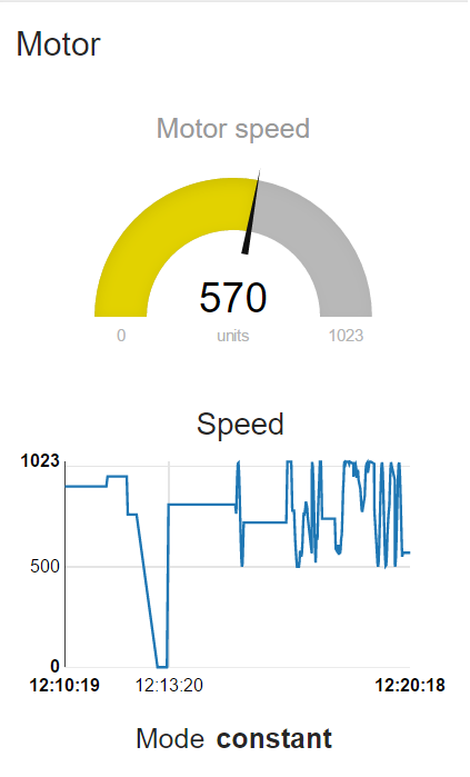
Controlling the vibrator prototype
After uploading the script above, open the serial monitor. After some time the NodeMCU will report “wifi connected”.
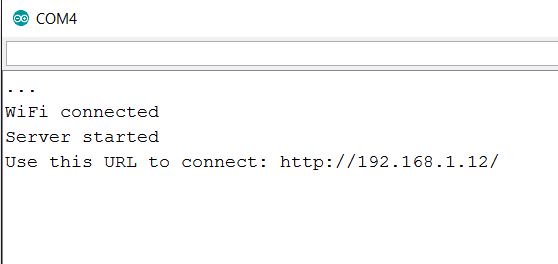 Now start a browser. Use the URL which the NodeMCU reported eg. http://192.168.1.12/
If your smart phone is connected to the same Access point as your computer is, you can use your smart phone to control the prototype, too.
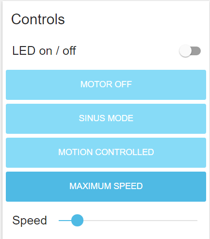
You can turn the LED on or off by pressing the “Turn On” and “Turn Off” buttons.
For controlling the motor you have 4 options
- motor on
- motor off
- sinus curve (the motor will speed up and slow down according to a sinus curve)
- motion controlled (more motion -> motor speeds up)
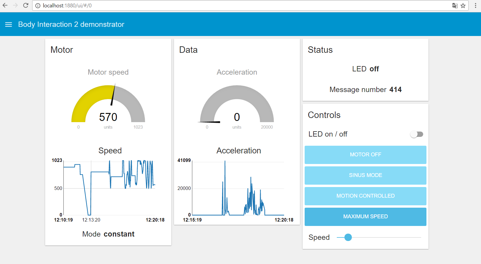
Summary
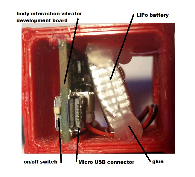
To build a vibrator prototype based on the ESP8266 MCU is very easy. You can use your Arduino IDE to upload scripts to the prototype. Then you can control the vibration motor through a browser. If you don’t want to use these external control options the vibrator prototype can be controlled by motion similar to the body interaction vibrator development board.
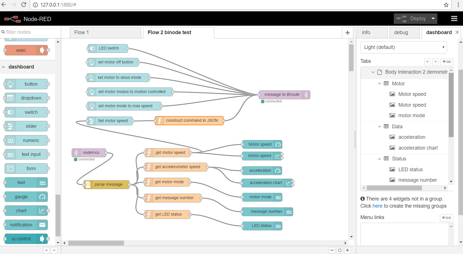
In this blog post series we will explore other interesting features of the ESP8266:
- the ESP8266 as an access point (no need for private or public access points)
- over the air (OTA) uploading of sketches (wireless – no USB connector needed)
- MQTT protocol & server
- Node-RED (visual IOT programming)
- review of development boards for building IOT vibrators
Go to the second part of the tutorial.


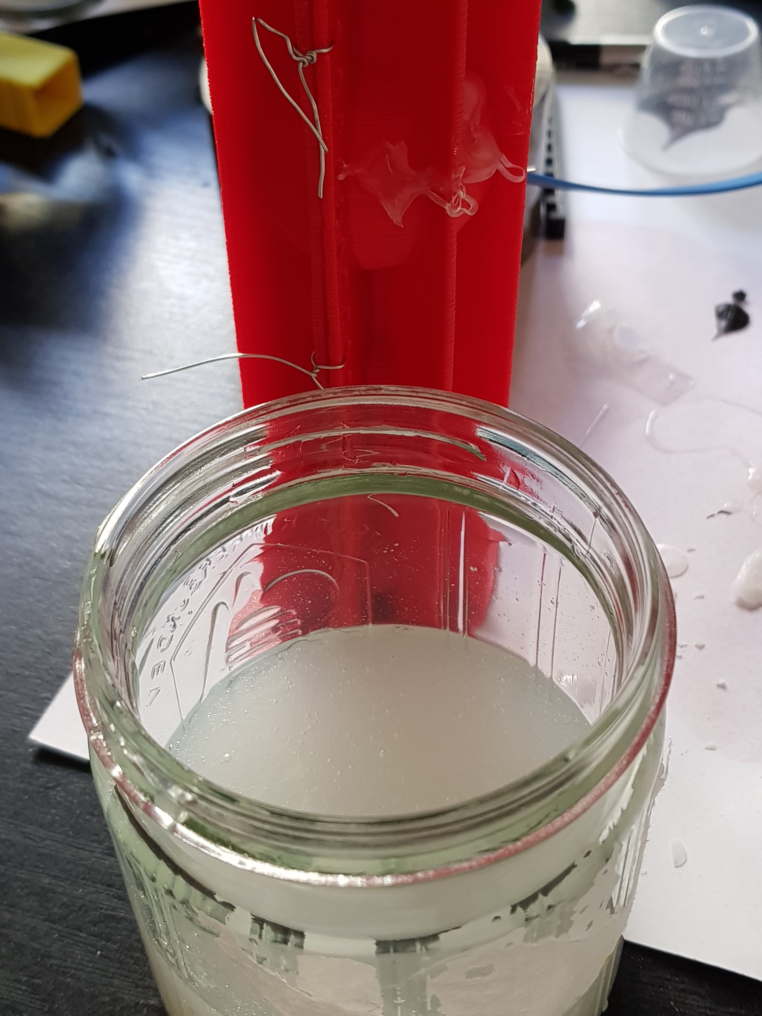


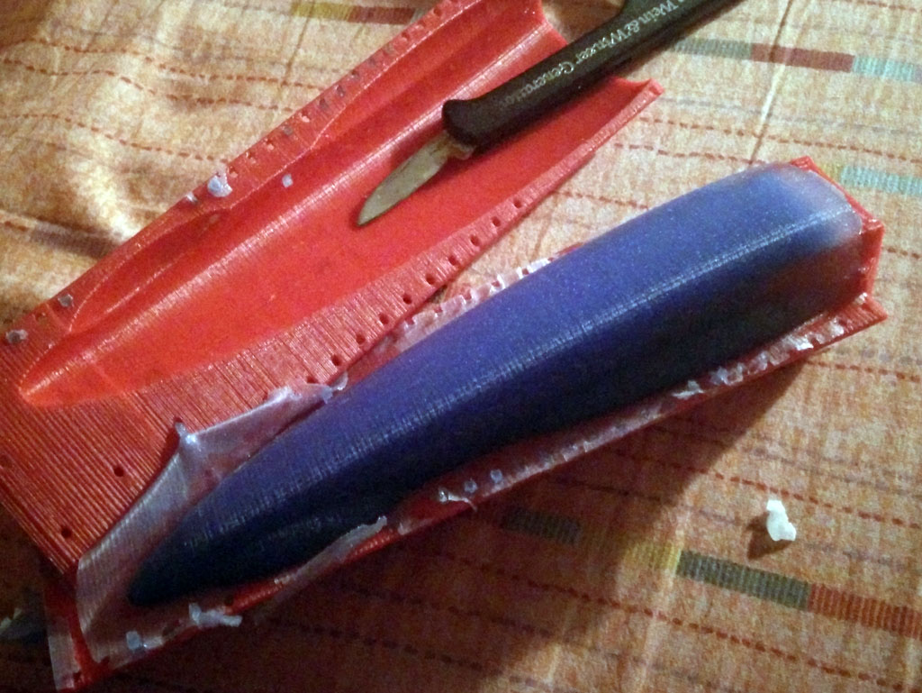
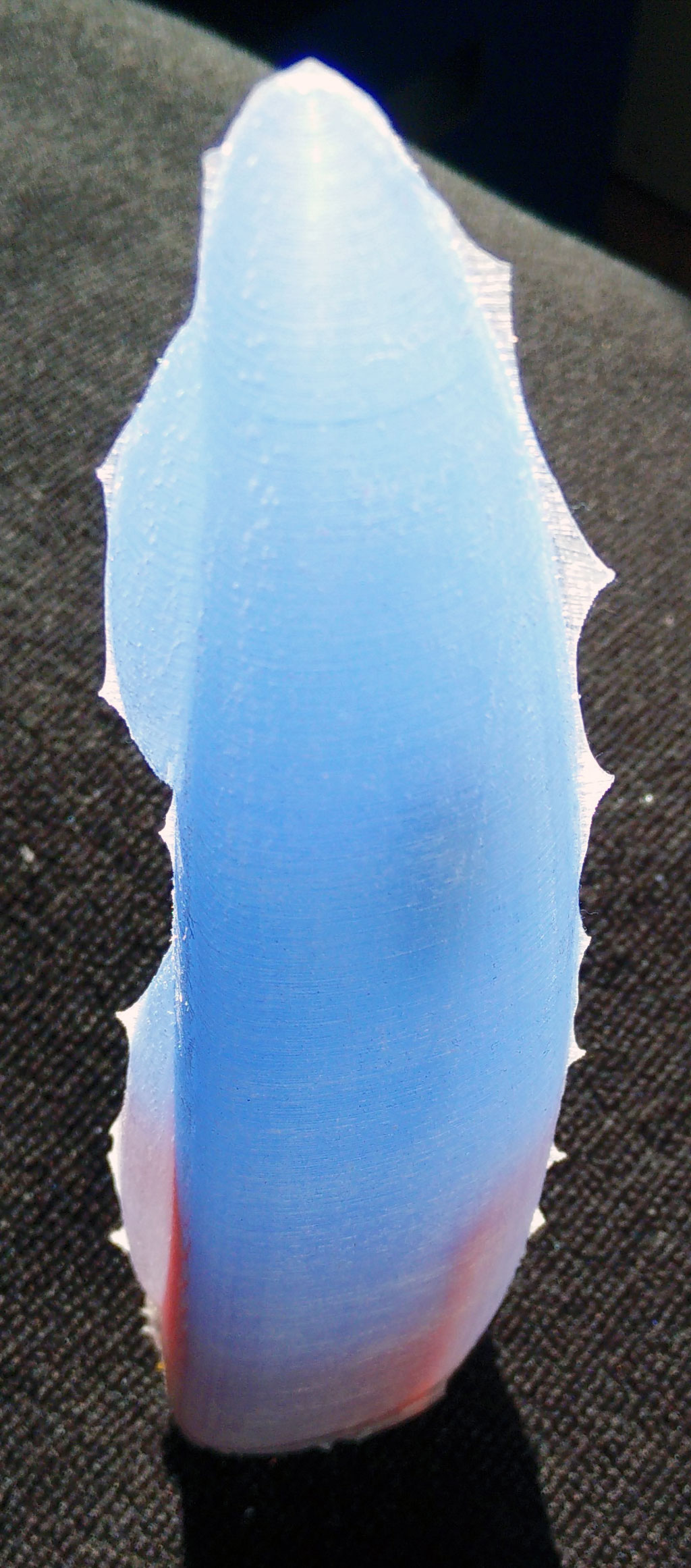
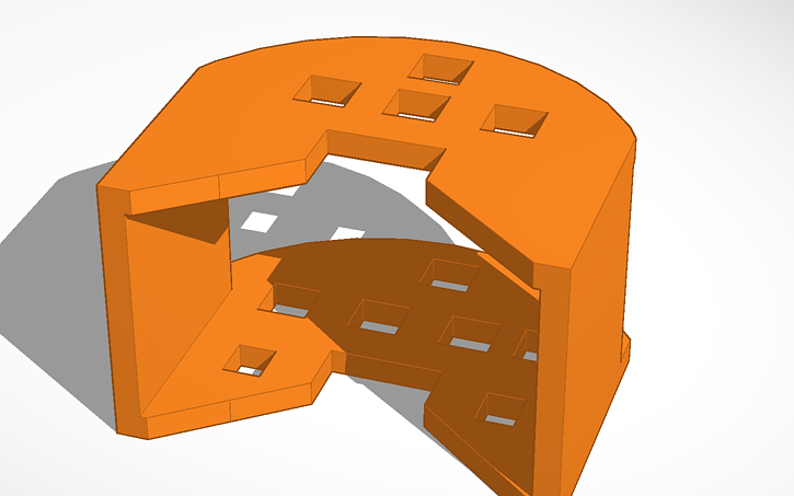
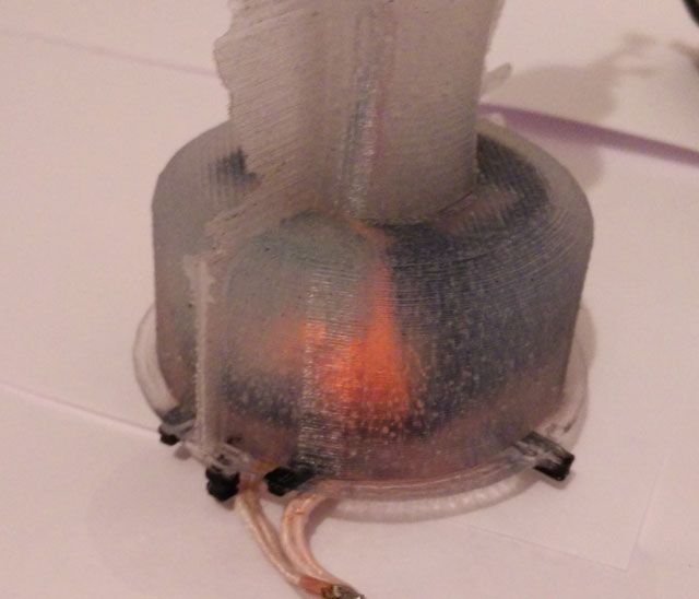
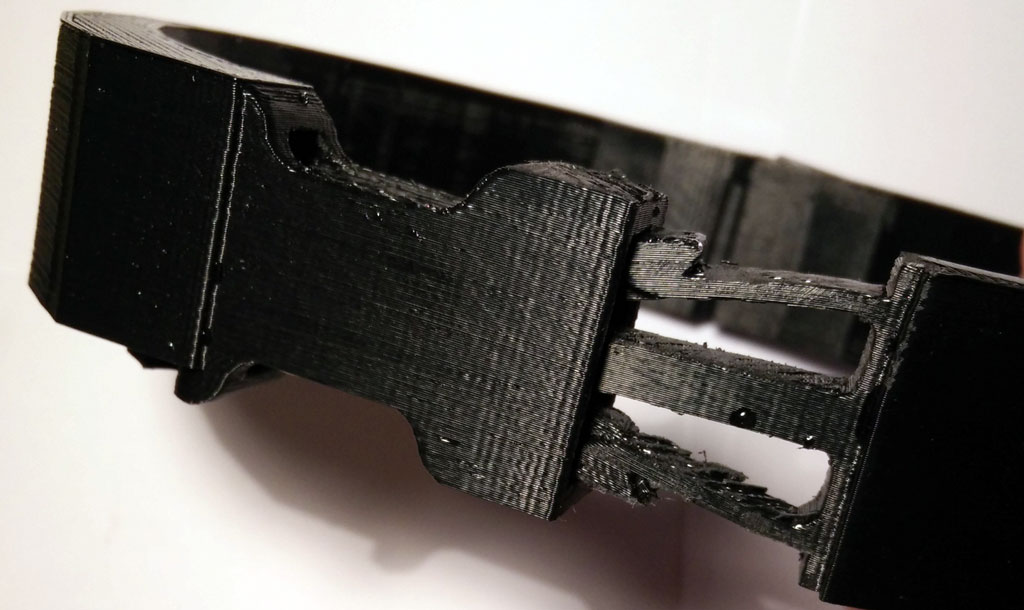
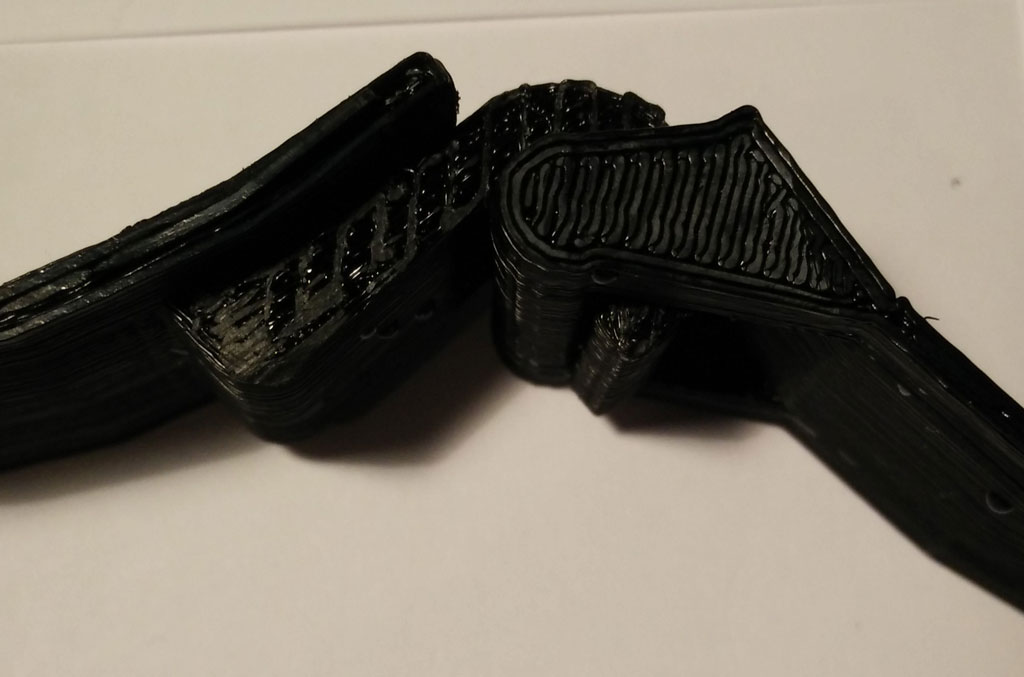
 Use some wax to fix little holes in the form where the printer failed. (These are the white spots)