
The UK-based Startup magazine is looking for the best female startup company. Touchy-Feely is on the short list and you can vote for them. Touchy-Feely develops educational electronic sex toy kits accompanied by workshops on basic and advanced sex toy topics. The founders have committed to building the funniest, most educational and pleasurable DIY electronics and coding kit out there.…
Category: development board
New body interaction 2 (BI2) boards available
The BI2 vibrator development boards are available at Tindie. You have now 3 three options:
- PCB only 29$
- kit 39$: PCB + 2 motors + LiPo battery + 2 motors + 2 JST-SH connectors (BUT connectors not soldered /connected to the motors)
- complete kit 49$: the same as the kit but connectors soldered to the motors
If you now how to solder / connect wires: Please select the kit as I am not good doing soldering.


The new BI2 black vibrator development board
The new black BI2 board is ready. I have a few assembled boards ready for shipping. Have a look at www.tindie.com
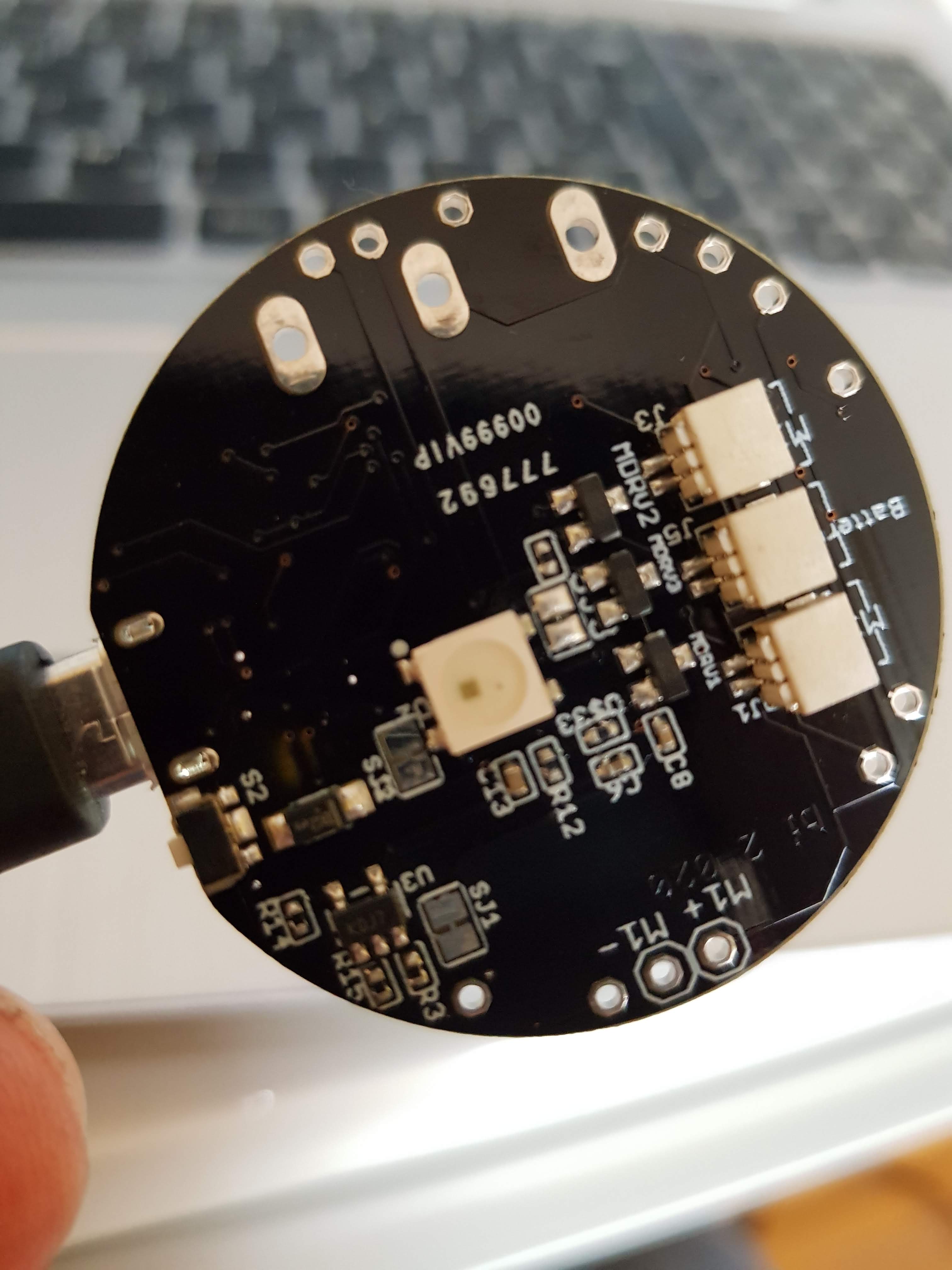
3 JST 1mm plugs (battery, motor 2, motor 3), LED, reset button, M+/M- is for motor 1

JST 1mm plug for motor 1, alternative RESET button
Features
- ESP8266 Microcontroller with WLAN
- MPU9250 (accelerometer, gyroscope)
- LiPo battery charging
- 3 motors can be connected (simple motor driver circuits)
- 1 WS2812B LED – a colourful LED (16 Mill. colours). They are commonly known as Adafruit Neopixel – a strip or a ring of individual programmable LEDs (when use the WS2812B only two motors can be connected)
- design based on the great Adafruit Feather Huzaah ESP8266
- vibration motors and LiPo battery can be easily connected with JST 1mm connectors
- two reset buttons (the button next to the USB connector can be overmolded)
- USB connector for battery charging and code uploading
- programmable with the Arduino IDE or NodeMCU
- white LED for indicating charging
- standard LED (yellow) on GPIO00
- round 40mm diameter

There are 3 free GPIO ports. Standard layout are for driving 2 motors (GPIO 12 = M2, GPIO 13 = M3) and 1 LED (GPIO14). Alternatively you can use 3 motors (GPIO12,13,14) but no LED.
Standard: SJ2 not connected, SJ3 connected
Alternative: SJ2 connected, SJ3 not connected
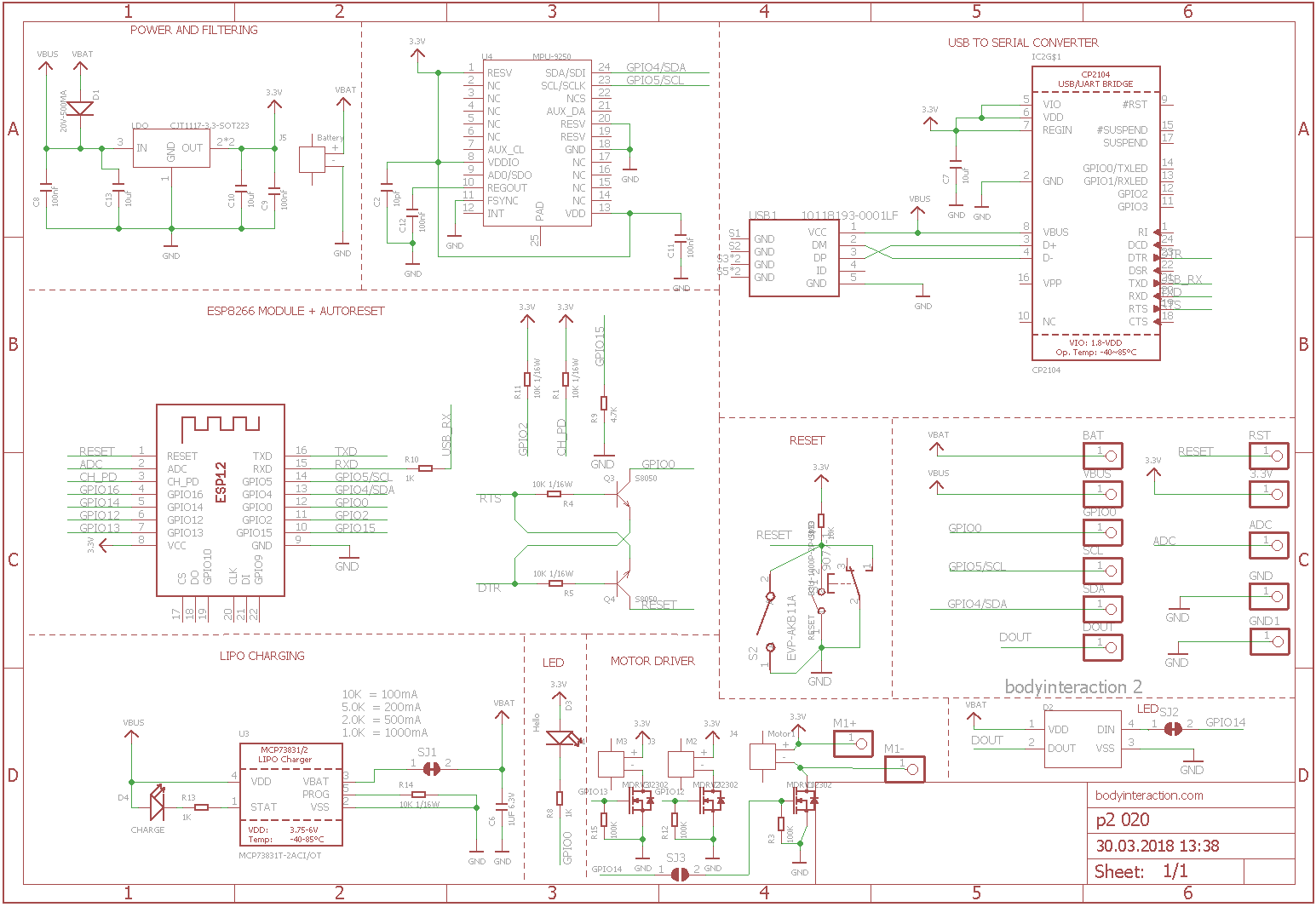
Here is the schematic which is adapted from Adafruit.
References:

BI2 – building a silicone sex toy
Now let’s build the first ESP8266 vibrator. I use the reliable design from this blog post and the new BI2 board. The new BI2 board can be controlled from any smart phone or computer.
As the BI2 board is round there is no need to build a case for the PCB and the LiPo. The easist way is to glue the battery directly on the ESP8266. Connect the battery and one or more vibration motors with the BI2 board.

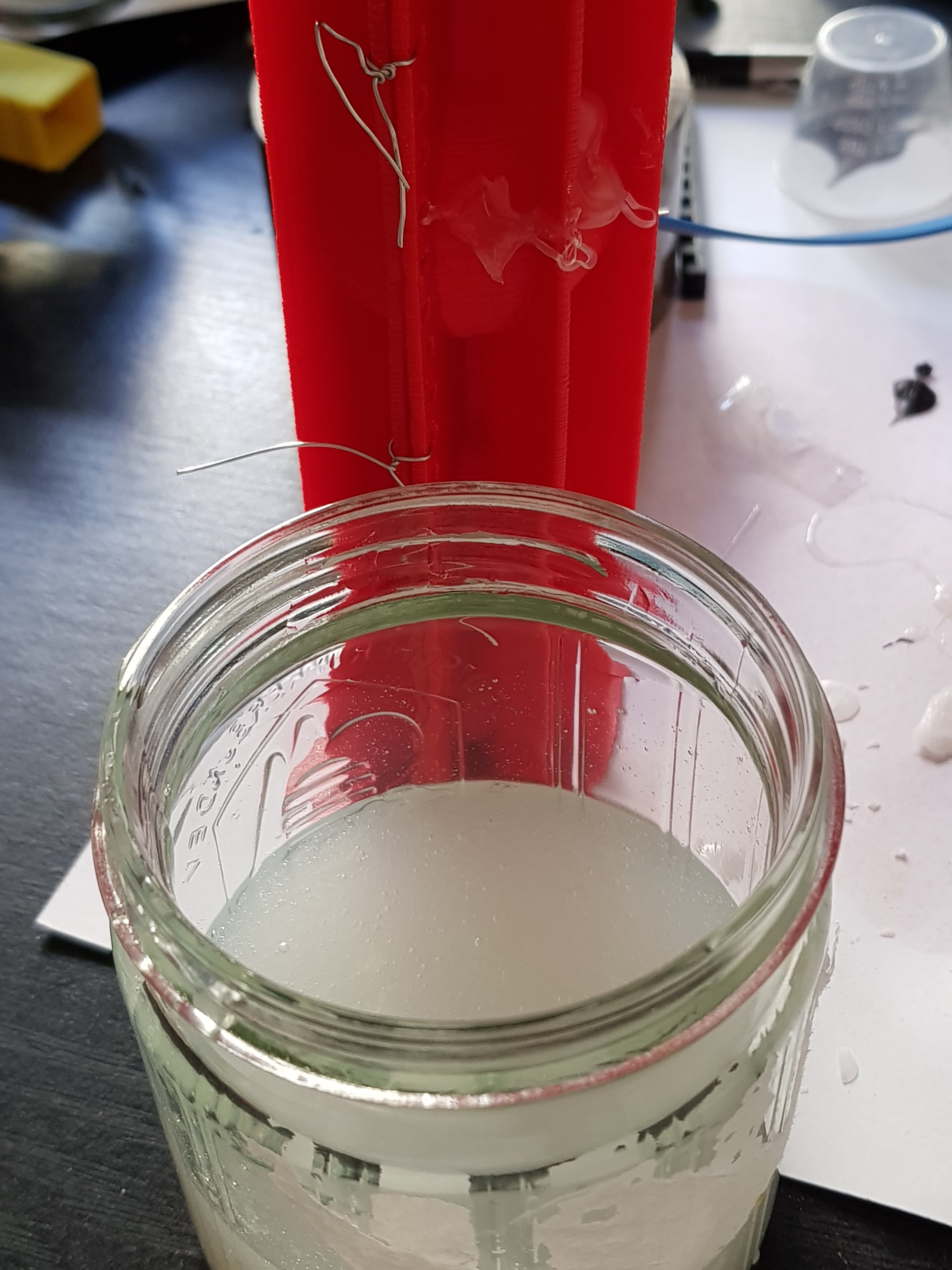
The form consists of two parts which are fastened together with tinker wire. Before you have to insert the board with the vibration motor(s) and the battery. Therefore I used a handle. The handle could be put on top of the form. Then fix a USB connector to the handle. Plug in the BI2 board. Fasten the second half of the form.
Very important: The USB micro connector on the board must be protected from the silicone. When silicone flow between USB plug and connector it will be impossible to pull out the plug. I use wax to seal the USB micro connector. Read more here.

Now pour in the silicone, wait for some hours. And open softely the form.


Remove the overhanging silicone.
Here ist the Link to Tinkercad where you can edit the form and download STL files for your 3D printer: Download from Tinkercad: form, handle. Download ready to print zipped STL files.
Now build YOUR personal sex toy. Here you find the code for the ESP8266 as well as an IOT server application for quantifying your sex and remote control.

Making of an ESP8266 Vibrator Development Board – traps and pitfalls
About a year ago I made a ESP8266 based design for a vibrator development board including IMU, motor driver and battery charging. The design was based on the Adafruit ESP Huzaah, but I used components of Seeedstudio Open Parts Library. This is a library of parts (IC, connector, resistors) which are stocked at Seeedstudio especially for their PCBA (printed circuit board assembly) service. PCBA is really great. Instead of tinkering and soldering on your own you can send the design to Seeedstudio, they make the printed circuit board and assemble all parts. Unfortunately the main part – the ESP8266 microcontroller – was missing in the Open Part Library . So I turned to use the affordable ready-made WeMos ESP8266 boards (see here).
In June 2017 I took a closer look at the PCBA service. At that time the OPL offered two variants of the ESP8266. But even better: You could order almost any part. The difference between using OPL parts and other parts was the time for the assembly as it takes more time to order parts which are not on stock.
So I ordered two boards. The boards are round with a diameter of 5 cm (that’s the size of a wireless charging coil). As I had a coupon the two boards were only about 50US$. Including delivery! And even better: Seeedstudio delivers from a logistic company in Germany. So I had not to pay any taxes. Great. But… unfortunately … I made beginner’s mistakes…during design.

- Problem: As the board should be programmable by USB connection you need a USB to serial bridge eg. one of the FTDI ICs. This bridge has two important connections TX (transfer) and RX (receive). And the ESP8266 has the same TX and RX. But don’t connect them. Instead you have to connect RX to TX and vice versa. (Well I should have know, when I soldered null modems maybe 20 years ago or more…)
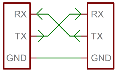
Taken from Sparkfun
- Problem: When using the serial monitor of the Arduino IDE you need another connection: RTS (ready to send). Unfortunately the used serial bridge – the FTDI FX230XS IC – had no RTS. (There is a circuit which works without RTS, but I didn’t know.)
- Problem: I used GPIO0 for driving the motor, that’s why auto reset doesn’t work. So I had to short-cut GPIO0 and GROUND for uploading a script.
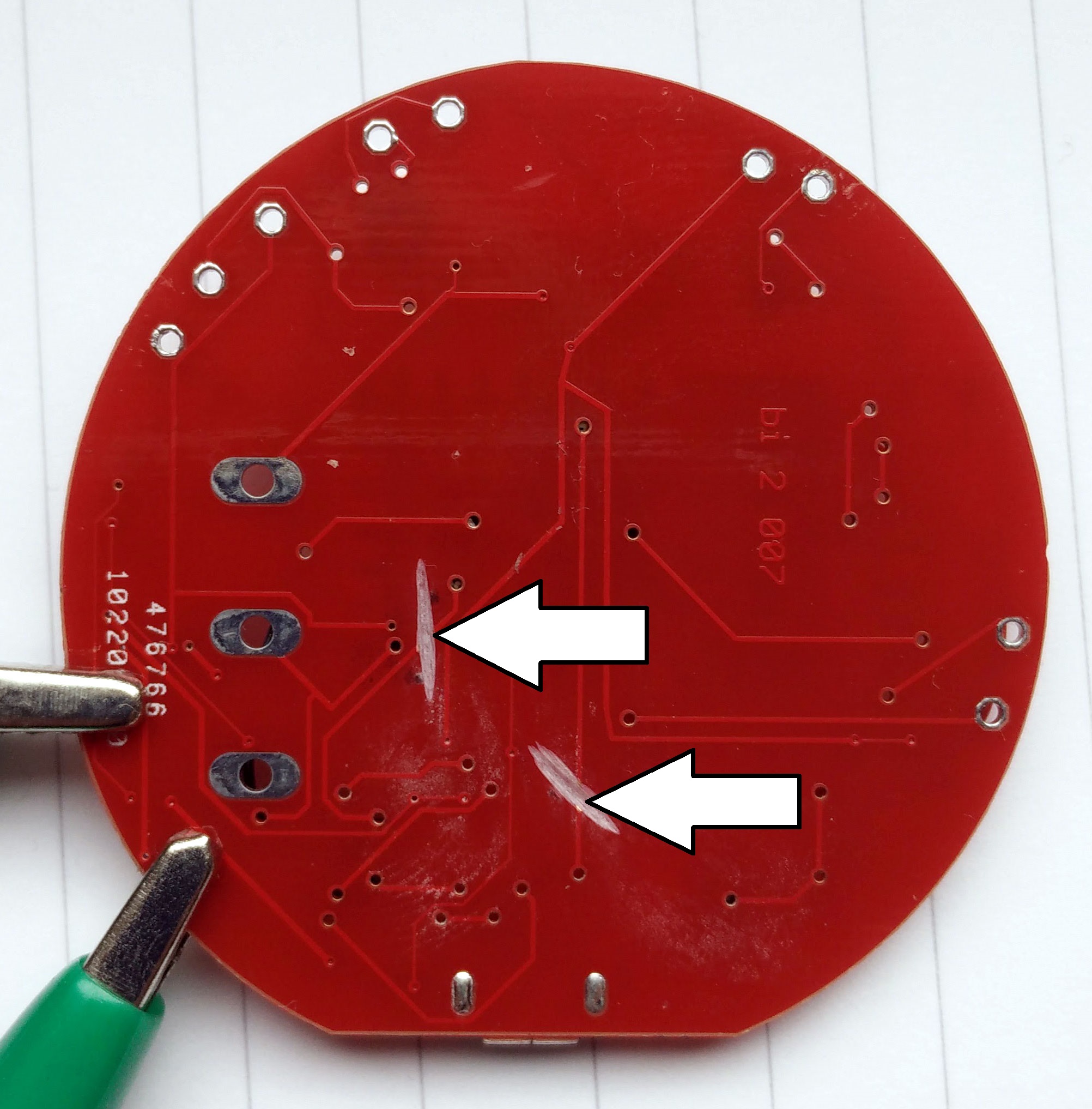
So I tried to fix the problem. At first I had to cut the wrong connections. On the bottom side of the board the RX and TX wires are quit good accessible. So I could cut them using a dremel.
In the next step I had to connect the RX and TX headers of the FTDI chip with the ESP 8266…
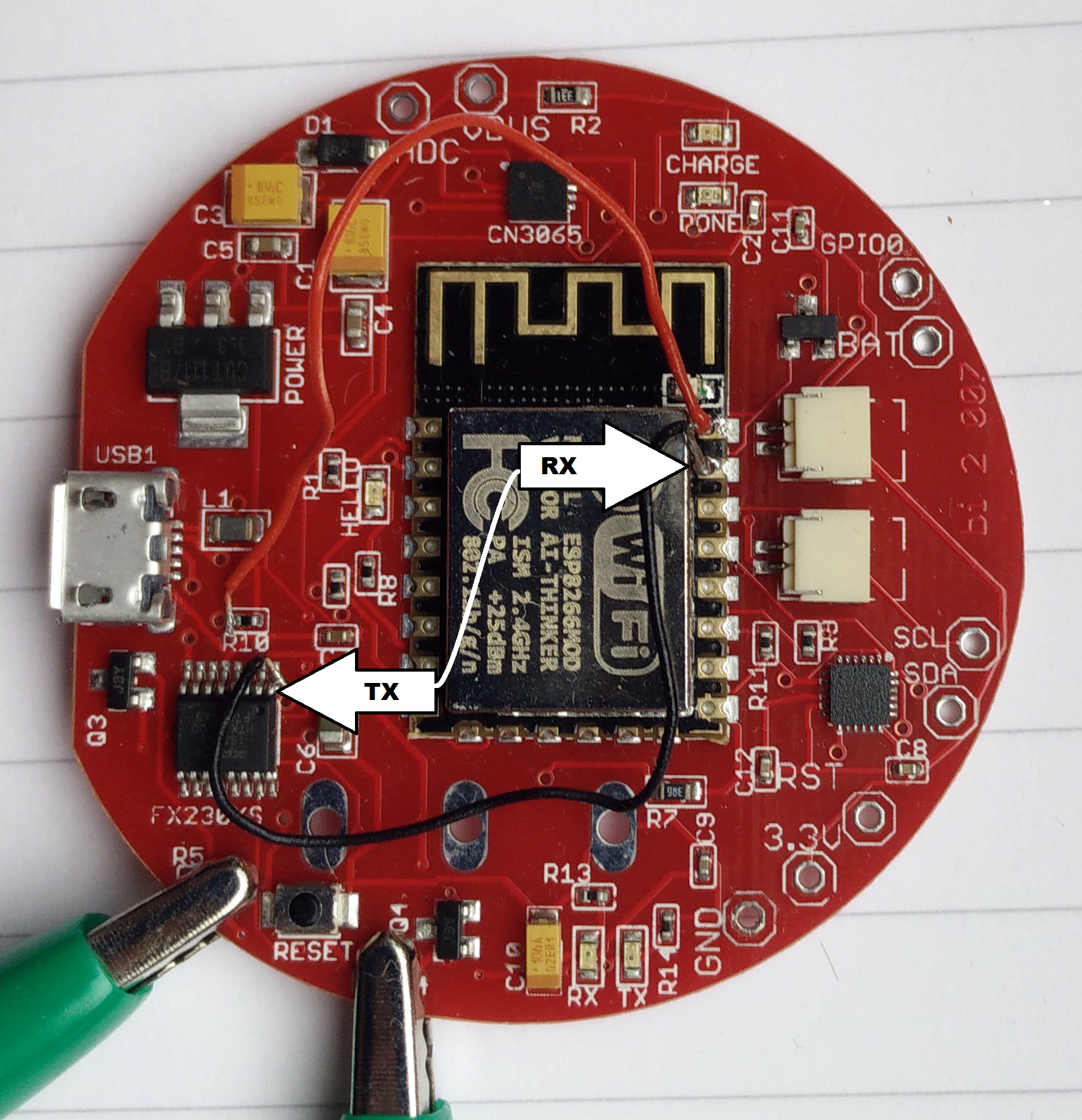
The green clamps were used to shortcut another wrong connection.
Finally upload with the Arduino IDE was possible, but no debugging using the serial monitor. Battery charging seemed to work, too, although this needs more time for testing. WiFi worked. Essentially I could upload a script which made one LED blinking. And I could start the WiFi manager.
Debugging such a complex thing like a ESP8266 without serial connection is almost impossible. But then I found RealTerm. This is the only terminal program for Windows where you have all options to use or not use serial sync mechanisms like DTR, RTS etc. It is made to make a serial connection work even if you have only TX, RX and GROUND.
Here you can decide to ignore RTS and/or DTR by pressing “Clear”. (Read more about this here.)
.![]()
And finally it worked. The ESP8266 sends debug text to the serial monitor. The transmission maybe scrambled, but it is still readable. Realterm – a really great tool for debugging serial connections.

Readings of the MPU9250 (accelerometer, gyro)
Probably it is more reasonable to use a bread board for the development of a design. But customizing an open source design on the PC and then get it assembled for a reasonable price – for me it’s like a dream come true. But as you see – all your efforts can be worthless.
 But I will do it again…
