An alternative to 3d-printed sex toys are silicone toys. For making such a sex toy you need a molding form, where you pour in the silicone. If you use Tinkercad to build the form for the balls motive, you may need more than one hour. If you are not experienced in 3d constrcution it may take days. That’s ok and can be fun as you can realize your fantasies step by step.
 But if you want to change a detail or want to resize some parts of it, it will take a long time as you have to unbuilt parts of the form, make changes and then reassemble. Sometimes building from scratch is faster.
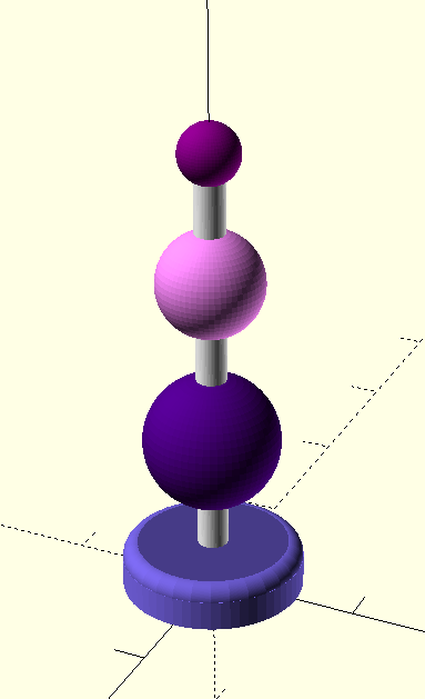
In the last blog post we have introduced OpenSCAD to construct a sex toy form. Now we want to build a hull for the sex toy for overmolding.
The basic idea is very simple:
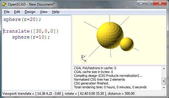
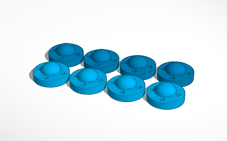
- Generate two forms. The smaller one has the size of the sex toy you want to make. The larger one will be the form where you pour in the silicone.
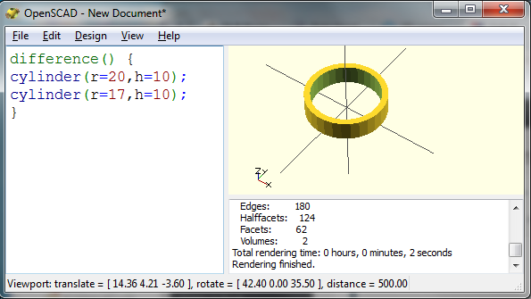
- Than use the OpenSCAD difference command which “subtracts” or cuts out the smaller form from the larger form.
But it is more complicated:
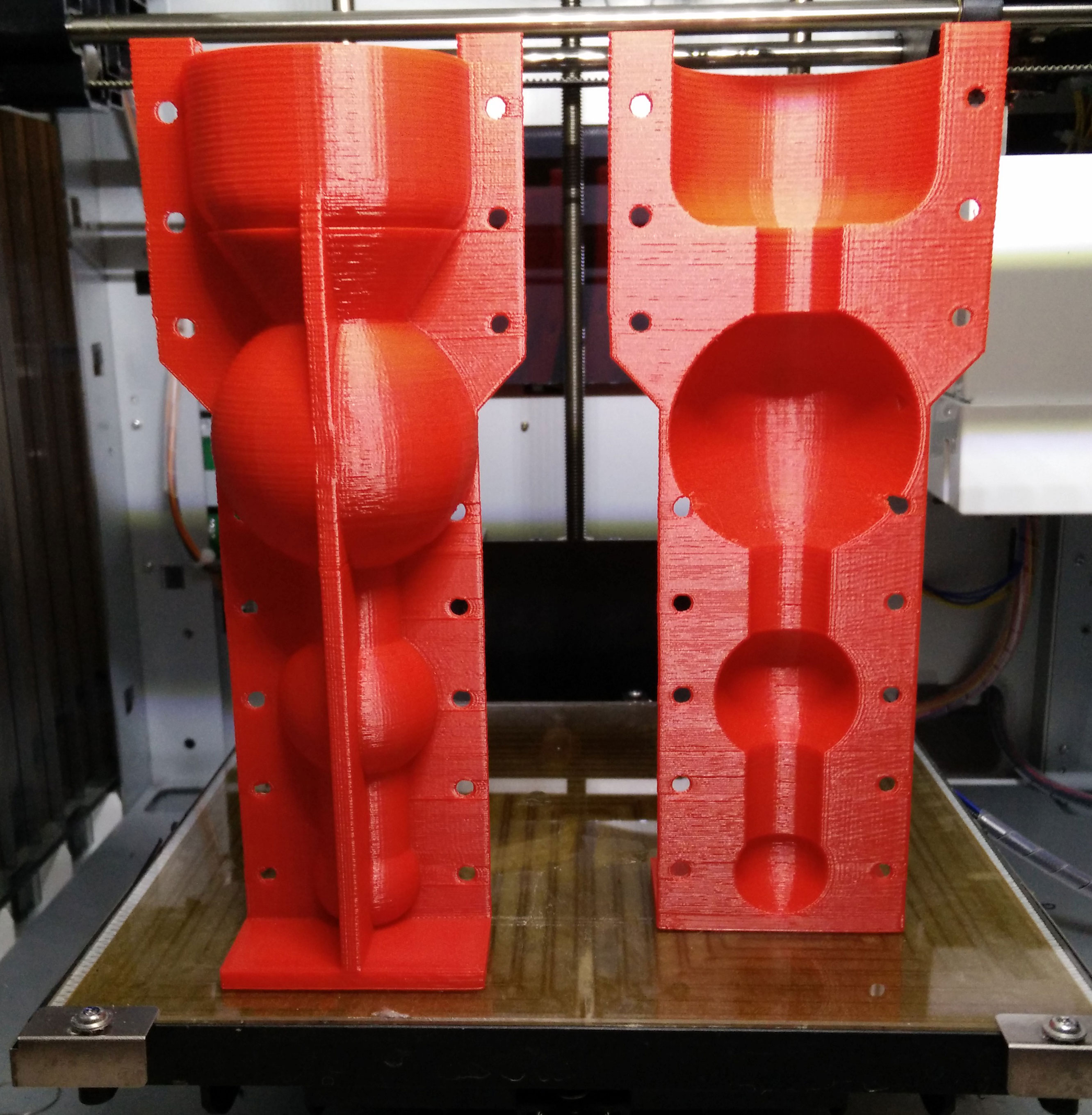
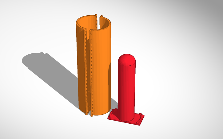
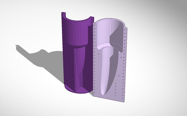
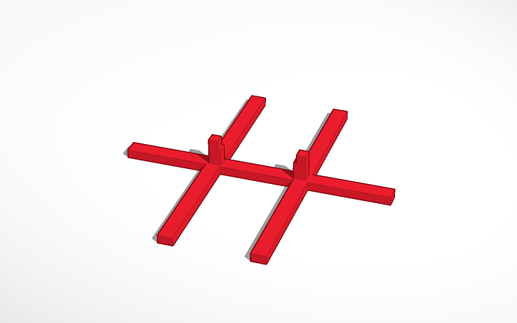
- You have to include a frame otherwise the form would fall over.
- You need two forms (A and b) so you could open the form after molding.
- Both forms must be fastened together when molding. Therefore you need holes for tinkering wire.
 We have created a solution for molding form generation which is as flexible as our OpenSCAD sex toy generator. In addition you can change the thickness of the frame. Therefore you have to change the variable frame_thickness.
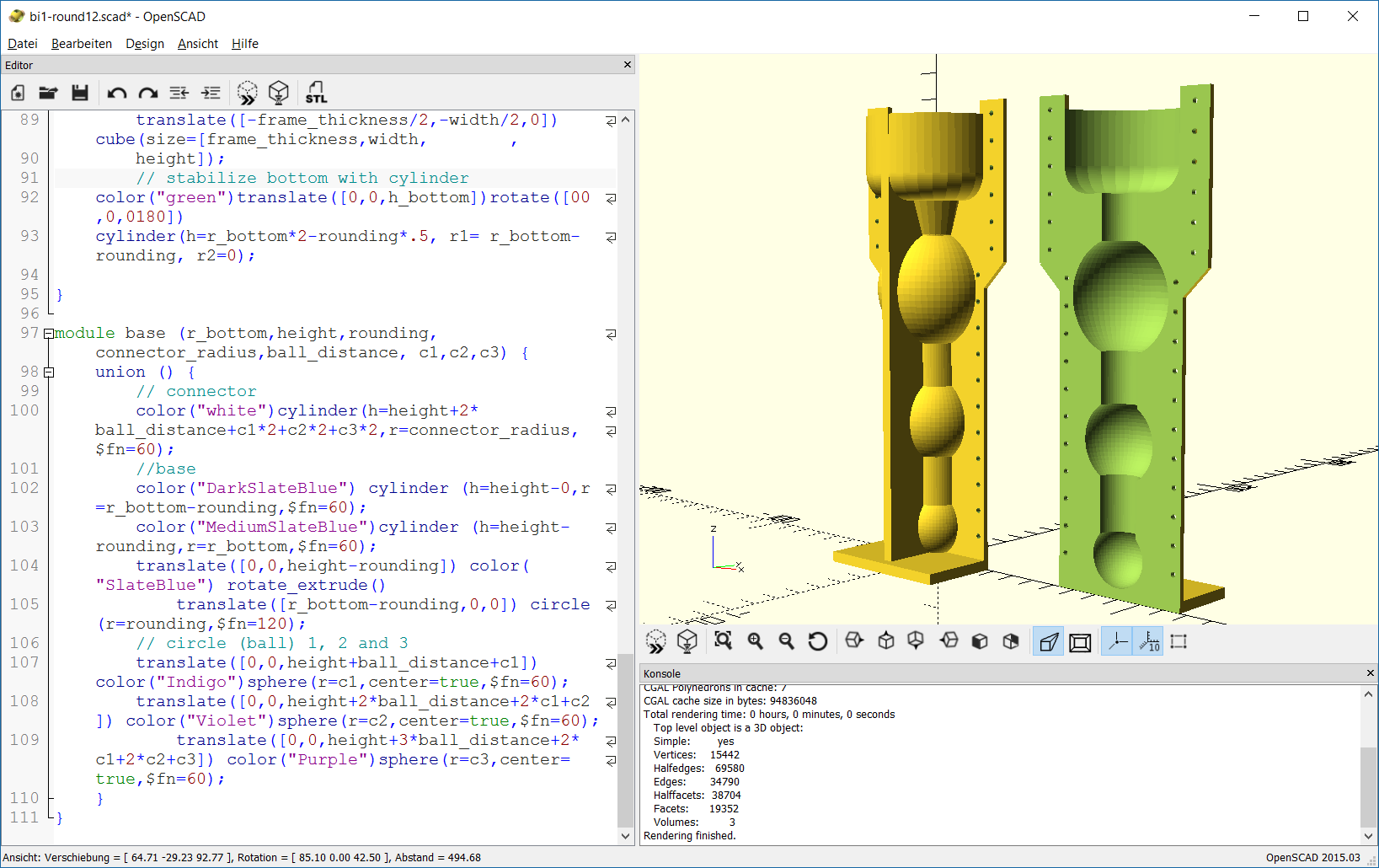
The SCAD script uses the module base which is already introduced. The generation of the frame is done in the module frame. The frame consists of a base plate and two supporting frames which stabilize the whole form. In addition there are extensions to the frame in the upper part of the form. These extensions will provide holes for fastening both forms.
The module complete_form constructs the form which is tricky. The union command is used to join the complete outer form and the frame. Now we have a filled form and have to remove the inner part. This is done by subtracting another complete form which is a bit smaller than the outer form. This is done with the difference command.
Another module hole provides all holes for the tinkering wire. At last we construct part A and part B of the molding form. Again the difference command is used to cut out one half of the form. This is done by subtracting a cube which is placed in the middle of the complete form. In addition the holes must be subtracted from the complete form.
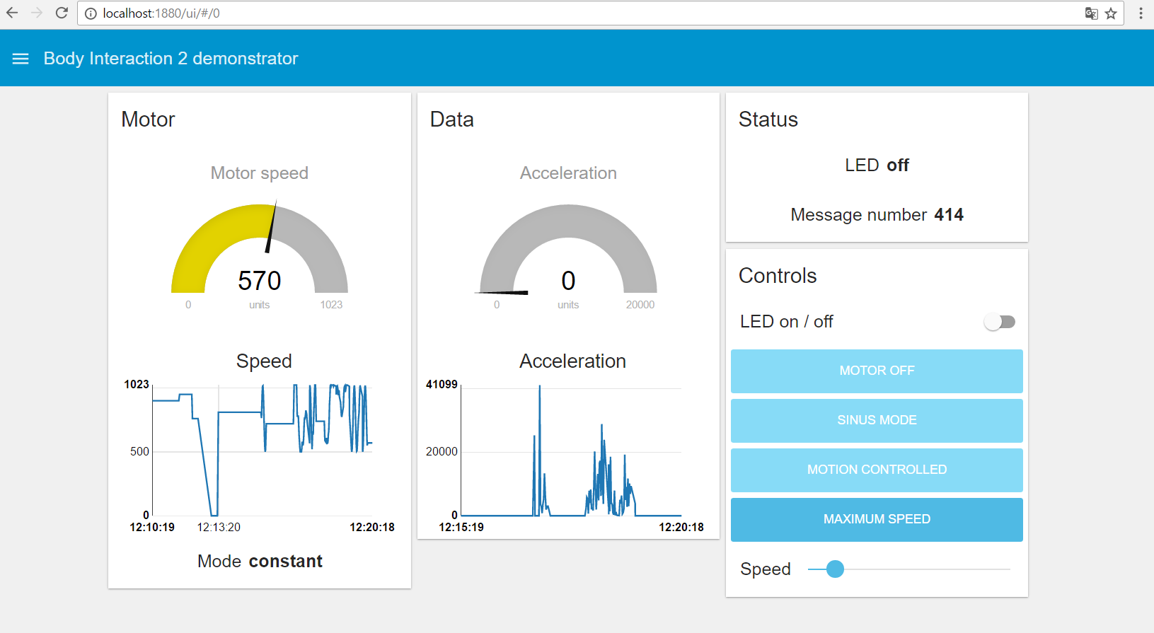
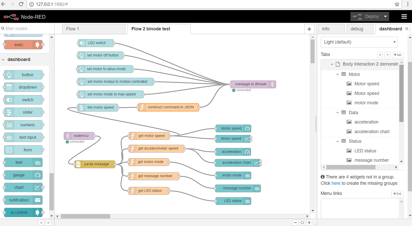
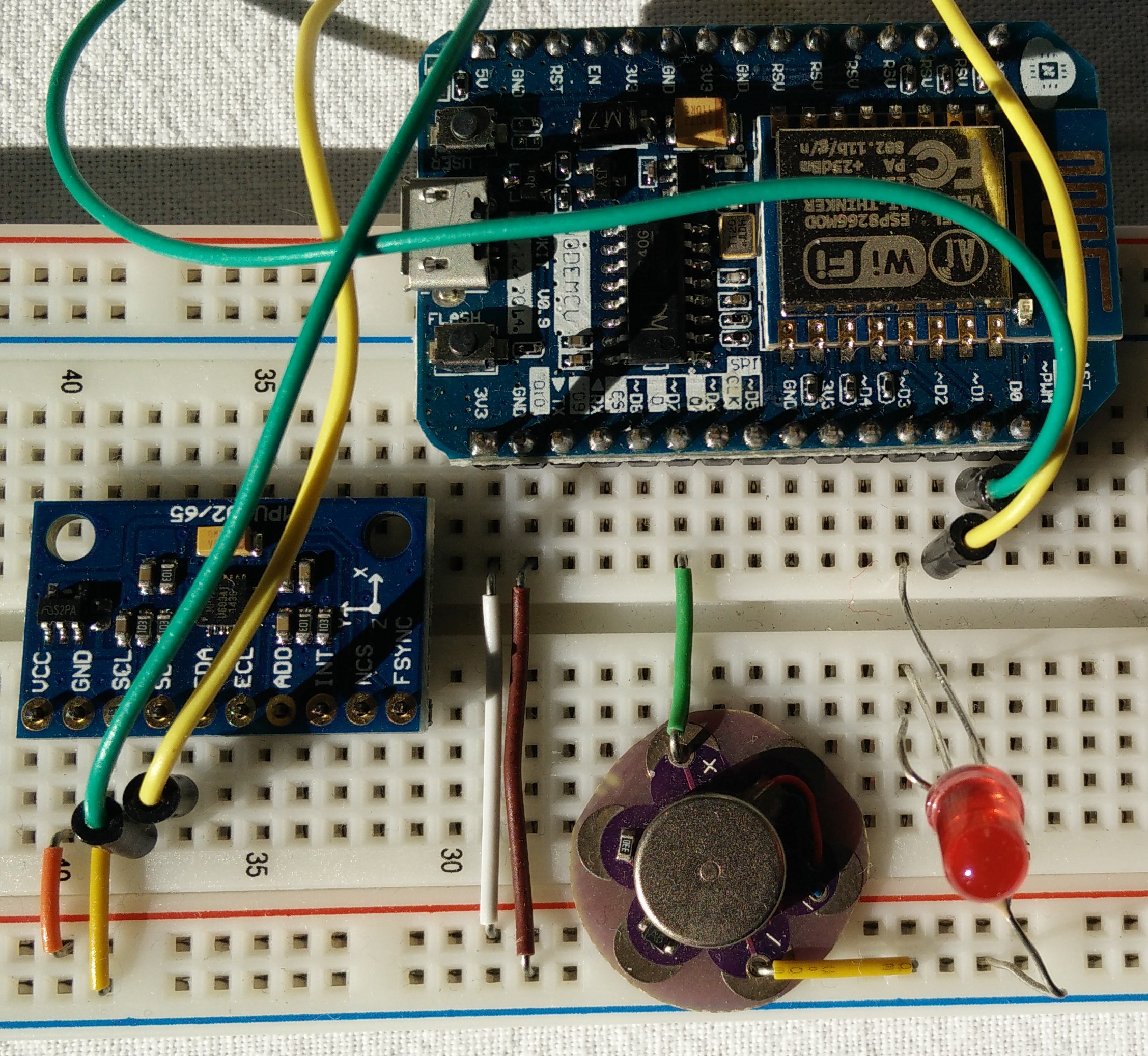
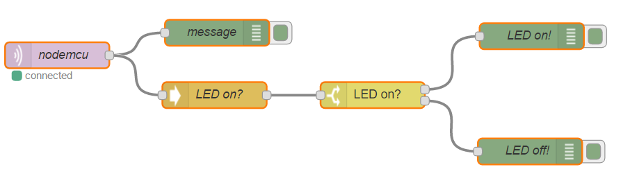
 You can build in the body interaction vibrator development board to make a vibrating dildo, controlled by motion or by another body interaction vibrator development board. Read more here.
Try out with the Thingiverse customizer.
Download the zipped SCAD file here: bi1-round12
Or copy and paste the source code to the SCAD software:
// bodyinteraction toy form and mold form generator
// radius of bottom part
r_bottom=25; // [15:5:80]
// height of bottom part
h_bottom=30; // [10:5:80]
// top rounding of bottom part
rounding=10; // [10:5:20]
// radius of ball 1
r_ball1=21; // [15:5:50]
// radius of ball 2
r_ball2=15; // [15:5:50]
//radius of ball 3
r_ball3=11; // [15:5:50]
// radius of connecting cylinders
connector_radius=8; // [10:2:20]
// distance between balls and bottom part
ball_distance=15; // [10:2:40]
// offset (thickness of hull)
o=2;
// thickness of frame
frame_thickness=4;

height=h_bottom+3*ball_distance+r_ball1*2+r_ball2*2+r_ball3*2; echo(height);


// form part A
translate([0,0,height+frame_thickness])rotate([0,180,0])
difference() {
 complete_form(r_bottom,h_bottom,rounding,r_ball1,r_ball2,r_ball3,connector_radius,ball_distance,o,frame_thickness,height);
union(){
 translate([-r_bottom-o-10,0,-5])
 color("red")cube([2*r_bottom+2*o+20,r_bottom+2*o,height+frame_thickness+5]);
 holes(height,h_bottom);
 }
}
//form part B
translate([90,0,height+frame_thickness])rotate([0,180,0])
difference() {
 complete_form(r_bottom,h_bottom,rounding,r_ball1,r_ball2,r_ball3,connector_radius,ball_distance,o,frame_thickness,height);
union(){
 translate([-r_bottom-o-10,-r_bottom-o-2-10,-5])
 color("red")cube([2*r_bottom+2*o+20,r_bottom+2*o+10,height+frame_thickness+5]);
 holes(height,h_bottom);
 }
}

module holes (height,h_bottom){
for (i=[h_bottom+30:10:height])
 translate([r_bottom-1,5,i])rotate([90,90,0])
 color("green")cylinder(h=15,r=1,$fn=20);

for (i=[0:10:h_bottom+20])
 translate([r_bottom-3+10,5,i])rotate([90,90,0])
 color("blue")cylinder(h=15,r=1,$fn=20);

for (i=[h_bottom+30:10:height])
 translate([-r_bottom+1,5,i])rotate([90,90,0])
 color("green")cylinder(h=15,r=1,$fn=20);
for (i=[0:10:h_bottom+20])
 translate([-r_bottom-6,5,i])rotate([90,90,0])
 color("blue")cylinder(h=15,r=1,$fn=20);
}

module complete_form (r_bottom,h_bottom,rounding,r_ball1,r_ball2,r_ball3,connector_radius,ball_distance,o,frame_thickness,height) {
 difference() {
 union() {
 base(r_bottom+o,h_bottom+o,rounding,connector_radius+o,ball_distance-2*o,r_ball1+o,r_ball2+o,r_ball3+o);
 //complete frame
 frame(2*r_bottom+2*o,o,height,frame_thickness,r_bottom,h_bottom,rounding);
 };
 base(r_bottom,h_bottom,rounding,connector_radius,ball_distance,r_ball1,r_ball2,r_ball3);


};
}

module frame(width,o,height,frame_thickness,r_bottom,h_bottom,rounding) {
 //plate
 translate([-width/2,-width/2-2*o,height]) cube(size=[width,width+2*o,frame_thickness]);
 //frame1
 translate([-width/2,-frame_thickness/2,0]) cube(size=[width,frame_thickness,height]);
 //frame 1 extensions
 translate([-width/2-010,-frame_thickness/2,-5]) color("blue")cube(size=[12,frame_thickness,60]);
 translate([-width/2-10,-frame_thickness/2,55]) color("red")rotate([0,45,0]) cube(size=[12,frame_thickness,20]);

 translate([+width/2-2,-frame_thickness/2,-5]) color("green")cube(size=[12,frame_thickness,60]);
 translate([+width/2+01,-frame_thickness/2,47]) color("green")rotate([0,-45,0]) cube(size=[12,frame_thickness,20]);
 //frame2
 translate([-frame_thickness/2,-width/2,0]) cube(size=[frame_thickness,width, ,
 height]);
 // stabilize bottom with cylinder
 color("green")translate([0,0,h_bottom])rotate([00,0,0180])
 cylinder(h=r_bottom*2-rounding*.5, r1= r_bottom-rounding, r2=0);

}

module base (r_bottom,height,rounding,connector_radius,ball_distance, c1,c2,c3) {
 union () {
 // connector
 color("white")cylinder(h=height+2*ball_distance+c1*2+c2*2+c3*2,r=connector_radius,$fn=60);
 //base
 color("DarkSlateBlue") cylinder (h=height-0,r=r_bottom-rounding,$fn=60);
 color("MediumSlateBlue")cylinder (h=height-rounding,r=r_bottom,$fn=60);
 translate([0,0,height-rounding]) color("SlateBlue") rotate_extrude()
 translate([r_bottom-rounding,0,0]) circle(r=rounding,$fn=120);
 // circle (ball) 1, 2 and 3
 translate([0,0,height+ball_distance+c1]) color("Indigo")sphere(r=c1,center=true,$fn=60);
 translate([0,0,height+2*ball_distance+2*c1+c2]) color("Violet")sphere(r=c2,center=true,$fn=60);
 translate([0,0,height+3*ball_distance+2*c1+2*c2+c3]) color("Purple")sphere(r=c3,center=true,$fn=60);
 }
}
Go to the first part of the SCAD tutorial

 In this series of posts we describe how-to make a vibrating sex toy which is part of the Internet of Things.
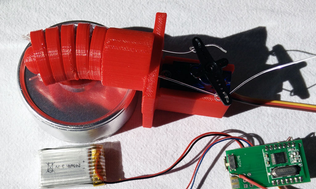
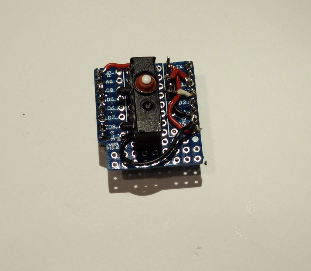
 Simply put the electronics inside so that the upper body of the switch is on the same level as the upper inlay. We use hot glue to fix the basic node.
 Then fix the receiver coil of the wireless charging module on top of the inlay. The next step is to fix the hanging at the inlay.
 Now fix the LiPo battery on the bottom side of the inlay using hot glue or similar. Fix the wires. Finally you might fix the wires of the vibration motor next to the middle of the LiPo battery.
 Use tinkering wire to fix both parts of the molding form.
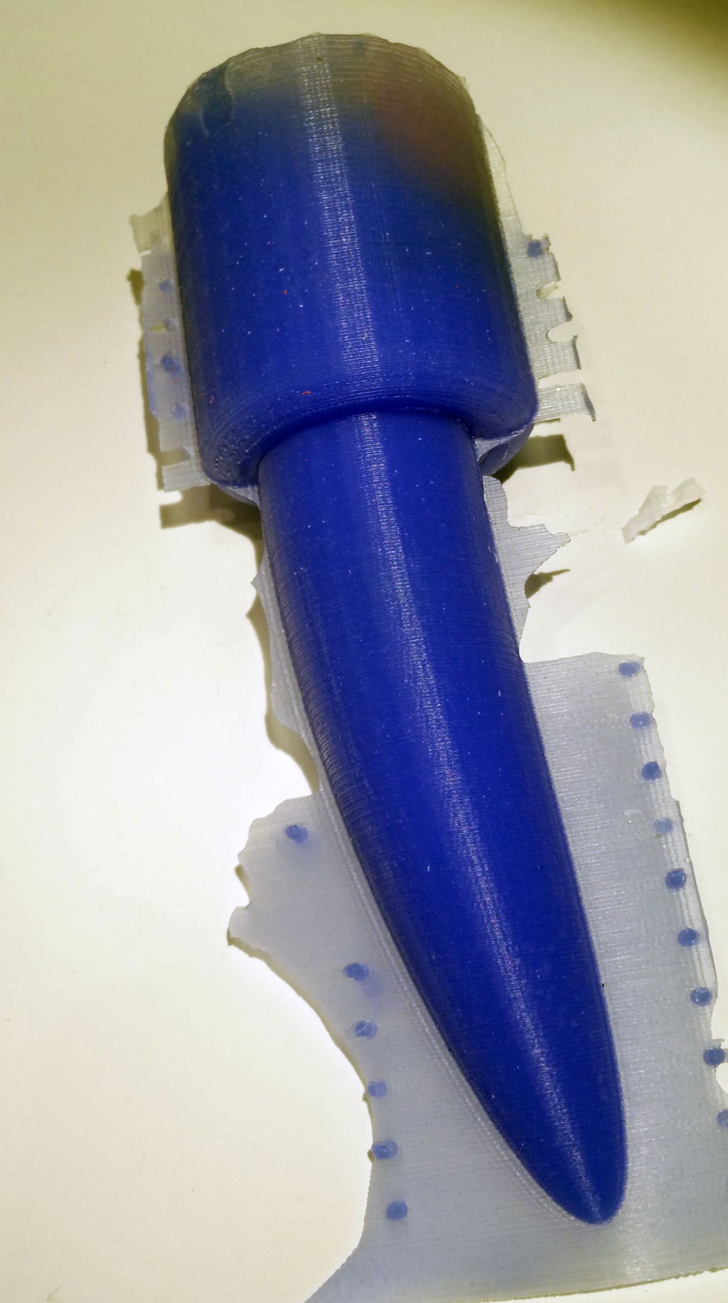
 Put the inlay in the form. Fix the hanging with a tape or similar. The motors shouldn’t touch the inner part of the form.
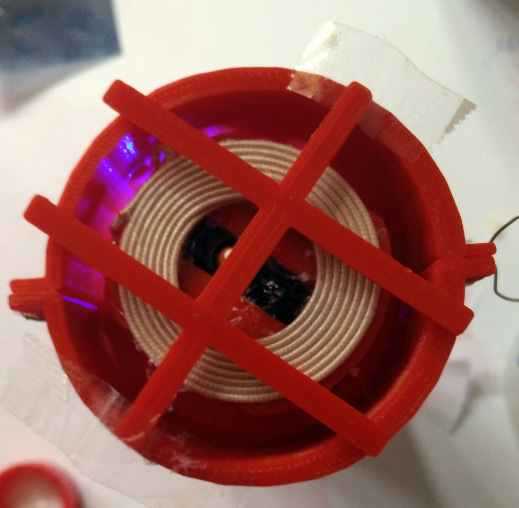 Now prepare the silicone. We use Shore A 45 silicone (approx. 250 ml) from Silikonfabrik.de. It is hard but still a bit flexible. You may add color, too. You have about 10 minutes to stir the silicone and poor it in the form.
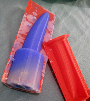


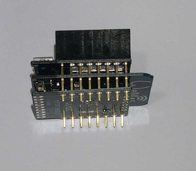


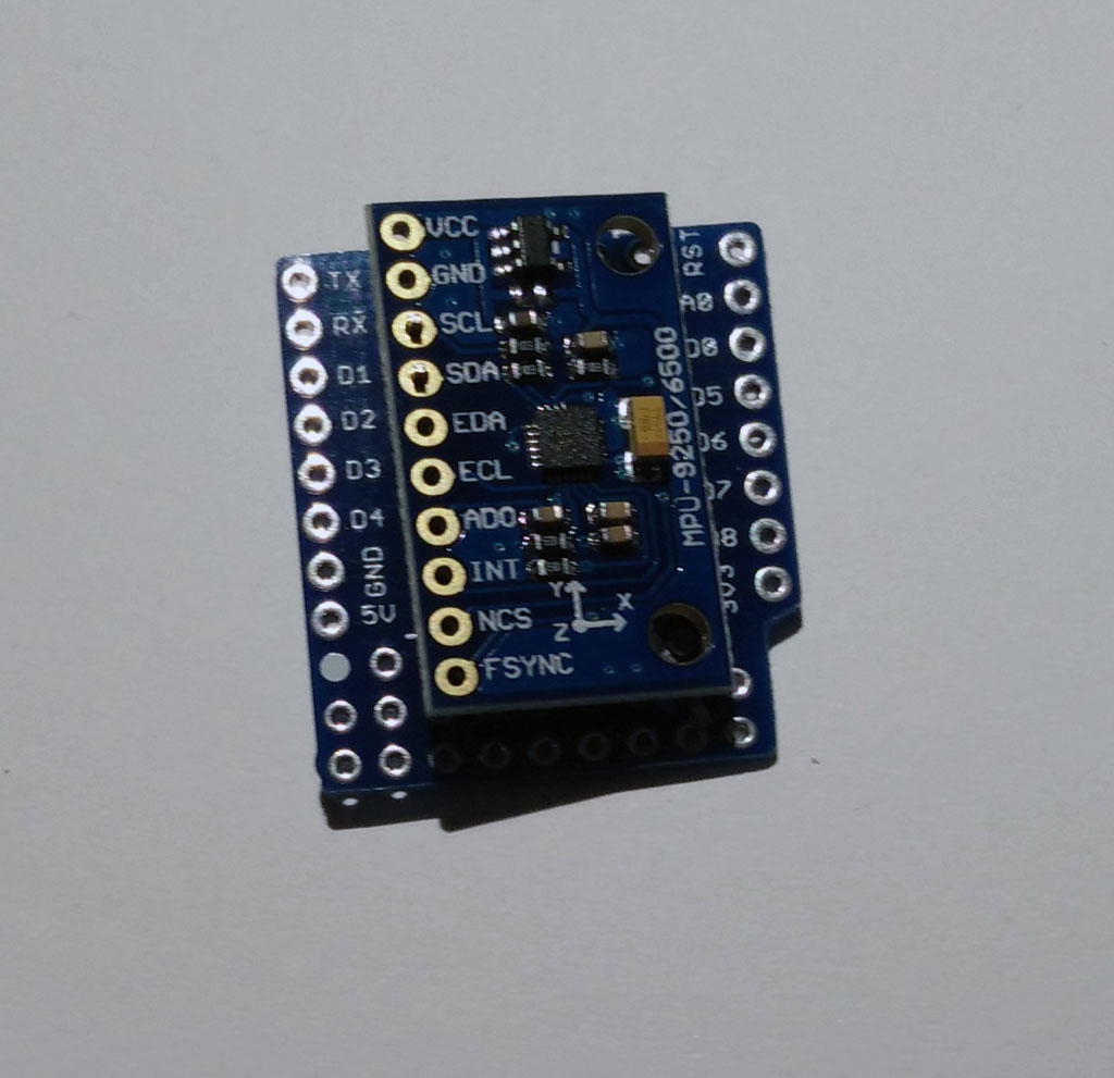
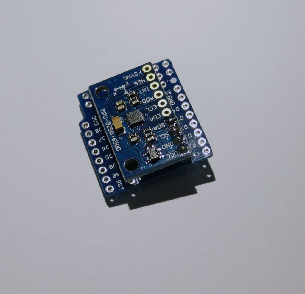
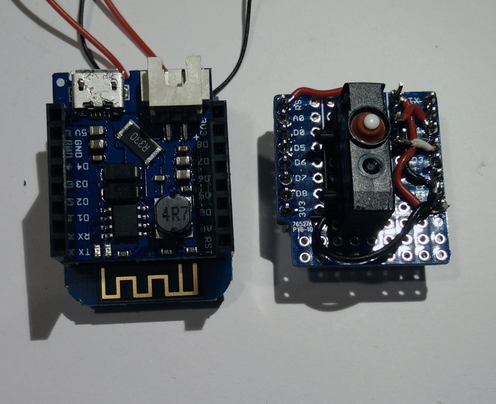

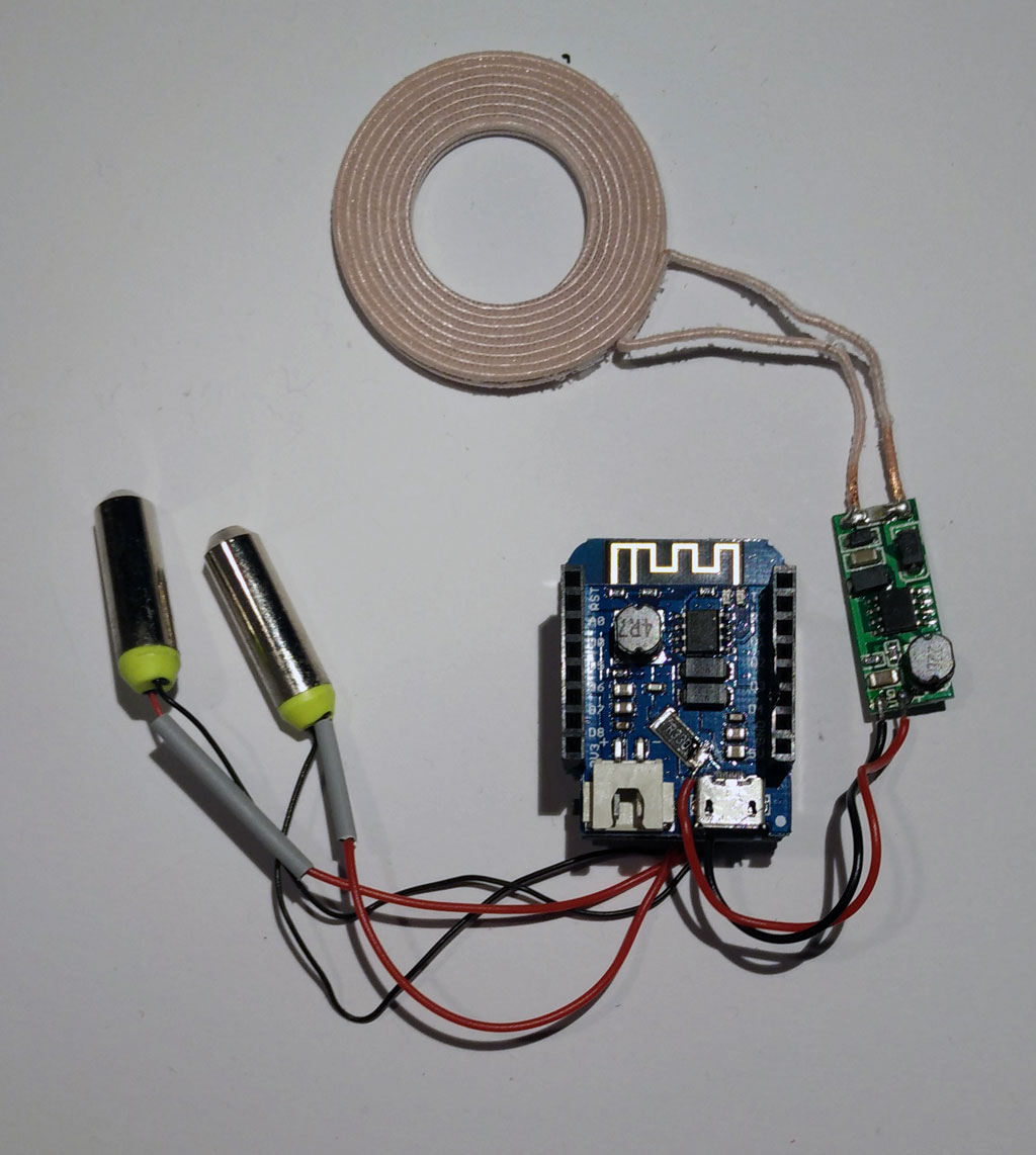

 Now stack the protoytping board on top of the battery shield. And connect the battery.
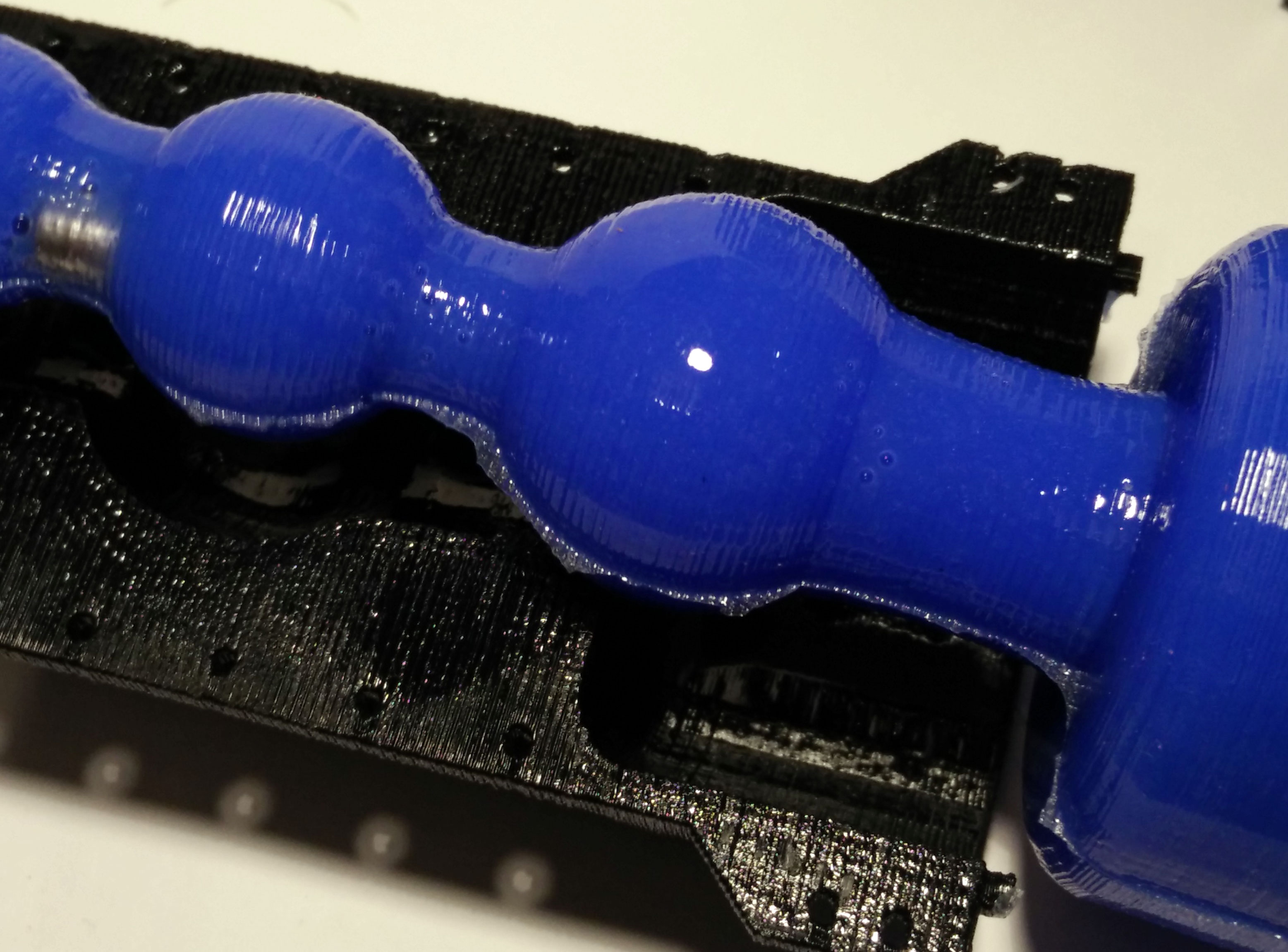
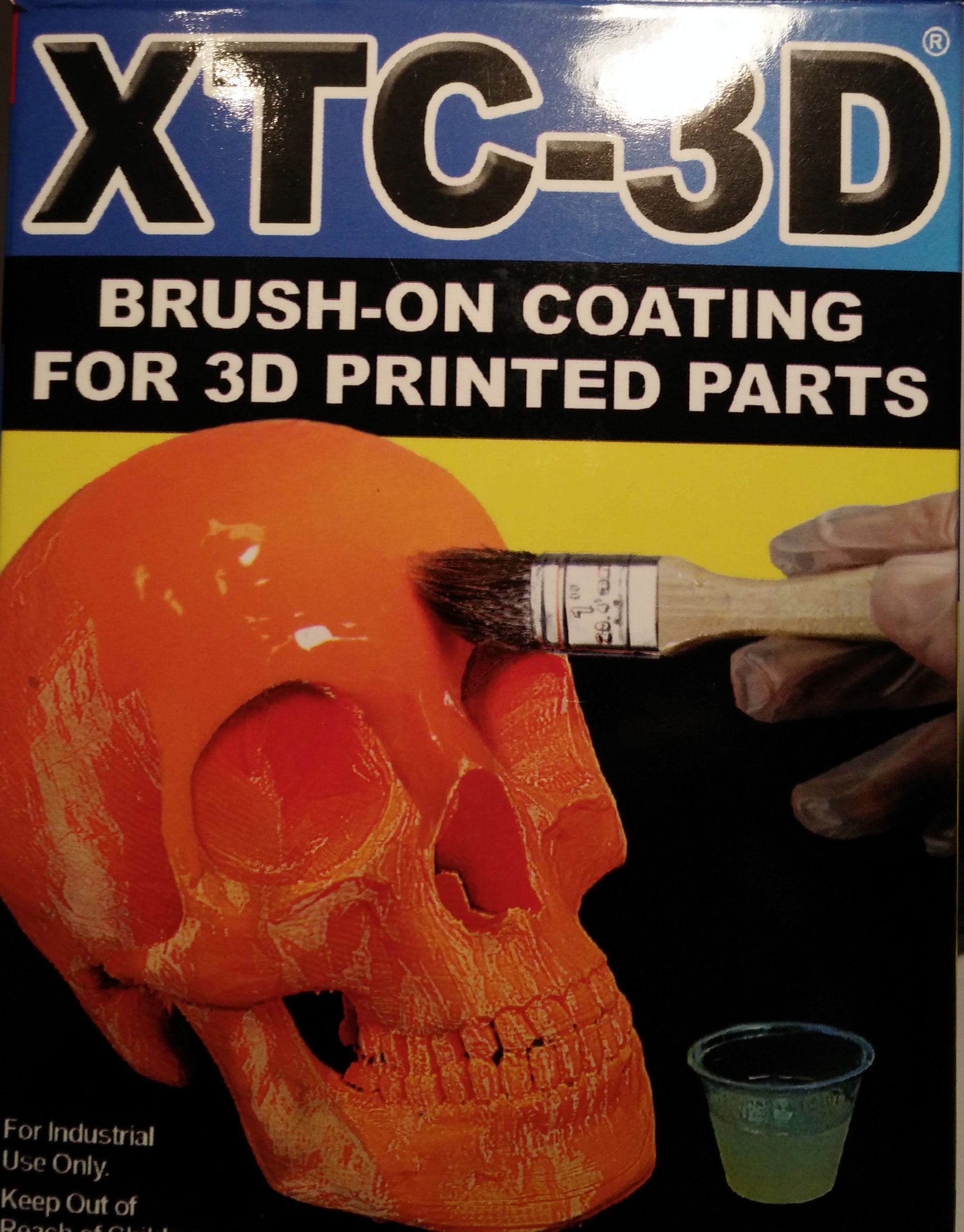
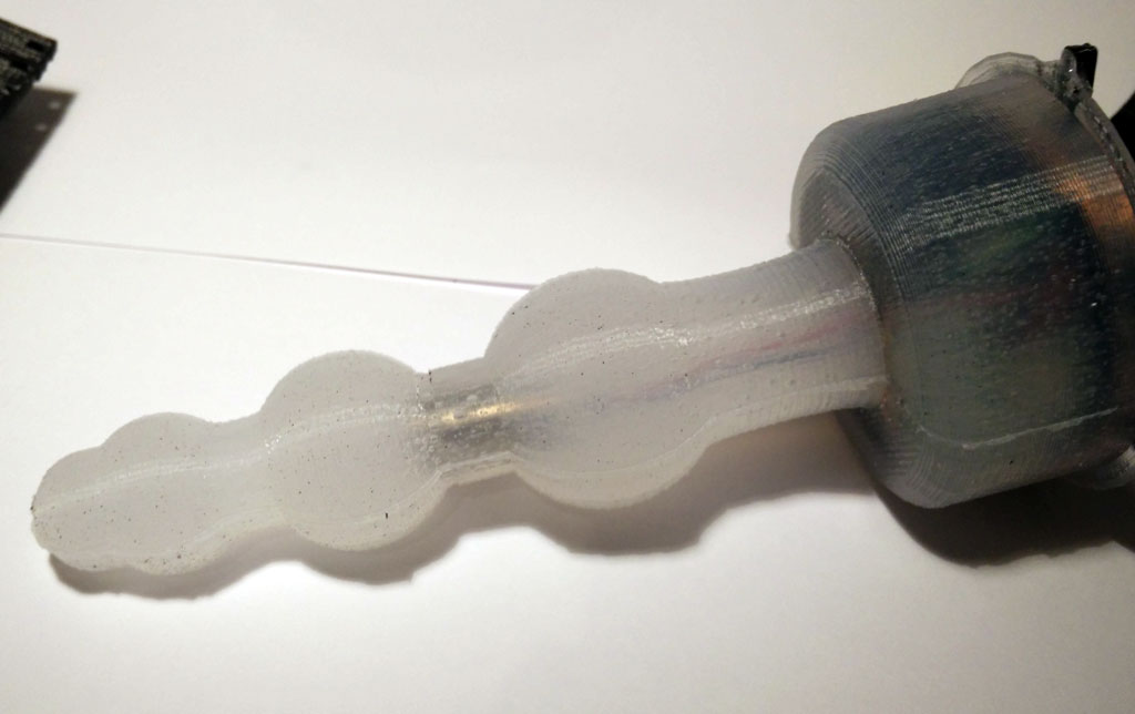
 But you can still see printer artefacts. To overcome this issue you could apply a thicker layer of XTC-3D. If you use a better printer than my daVinci 1.0 the “staircase effect” shouldn’t be a problem at all. Another problem are tiny – sometimes quite large – air bubbles. To remove this air bubbles you need a vacuum chamber. So it is still not perfect, but it works and looks quite good…