
The UK-based Startup magazine is looking for the best female startup company. Touchy-Feely is on the short list and you can vote for them. Touchy-Feely develops educational electronic sex toy kits accompanied by workshops on basic and advanced sex toy topics. The founders have committed to building the funniest, most educational and pleasurable DIY electronics and coding kit out there.…
Category: sextech
Programming the body interaction 2 (BI2) with Blynk part 1
This in an intro to using and programming the BI2 with the Blnyk app. Read here how to set up Arduino. For a more general basic intro (based on the body interaction 1 board) read here.
Pins
 The communication between app and BI2 microcontroller is realized by pins. The idea is very easy: Each widget in the Blynk app is connected to a physical pin of the microcontroller. Every microcontroller has several pins where you can connect other electronic parts like a LED or a vibration motor. For each pin you have to configure if it is a output or input pin. Output pins are for controlling actuators, like LED, motor or display. Input pins are connected to sensors, like buttons, temperature sensors, acceleration sensor. In addition each pin can be digital, analog or virtual.
Digital output pins can only set the actuator to on or off e.g. turning the LED on or off. Analog pins can set the actuator to a specific value in a given range. Usual this in done in the range [0..255] or [0..1023]. For a motor 0 will set the motor off, 50 may be make the motor move very slowly and 255 will be full speed. An analog output pin is sometimes called PWM. (PWM is a method to simulate an analog signal with a sequence of digital on/off signals.)
Digital input pins can read the position of a button (on/off). Analog input pins can read a value in a given range, e.g. the acceleration in the X-axis or the temperature.
So what you have to do to connect a widget to a pin? Just set the widget (e.g. on/off switch widget) to the pin you want to set on/off (e.g. a pin which is connected to a LED). That’s all. No programming required. All you need is this small program which must be uploaded to the microcontroller with the Arduino IDE.
The body interaction 2 use the ESP8266 microcontroller. There are 16 pins, all could be used as digital or analog, input or output. But only pin 12 and 13 are free to use (the rest if for internal communication). Pin 14 is connected to the LED WS2821B.
The Arduino sketch
The first 3 lines are for configuring Blynk and using two libraries. The 3 variables auth, ssid and pass are defined. (The variables are from thy type char (=character) and in this case it is not only one character but an array which you can see by the “[” and “]”. Here you have to add your AUTH token from the Blynk app, and SSID and password from your local WLAN/WIFI.
#define BLYNK_PRINT Serial
#include <ESP8266WiFi.h>
#include <BlynkSimpleEsp8266.h>

char auth[] = "XXXXXXXXXXXXXXXXXXXXXXXXXXX";
char ssid[] = "XXXXXXXX";
char pass[] = "XXXXXXXX";
Each Arduino program consists of a setup and a loop procedure. The setup is called only one time when the microcontroller is started (or connected to a battery). It is used to initialize the microcontroller, in this case Blynk is started. The loop will be called indefinitely and all statements are executed in the given order. To get Blynk running you have to call Blynk again and again (“Blynk.run();”). According to the Blynk manual, you should not add a delay() function here, because this could disturb the communication between the app and the microcontroller.
void setup() {
  Blynk.begin(auth, ssid, pass);
}

void loop() {
  Blynk.run();
}
Virtual pins
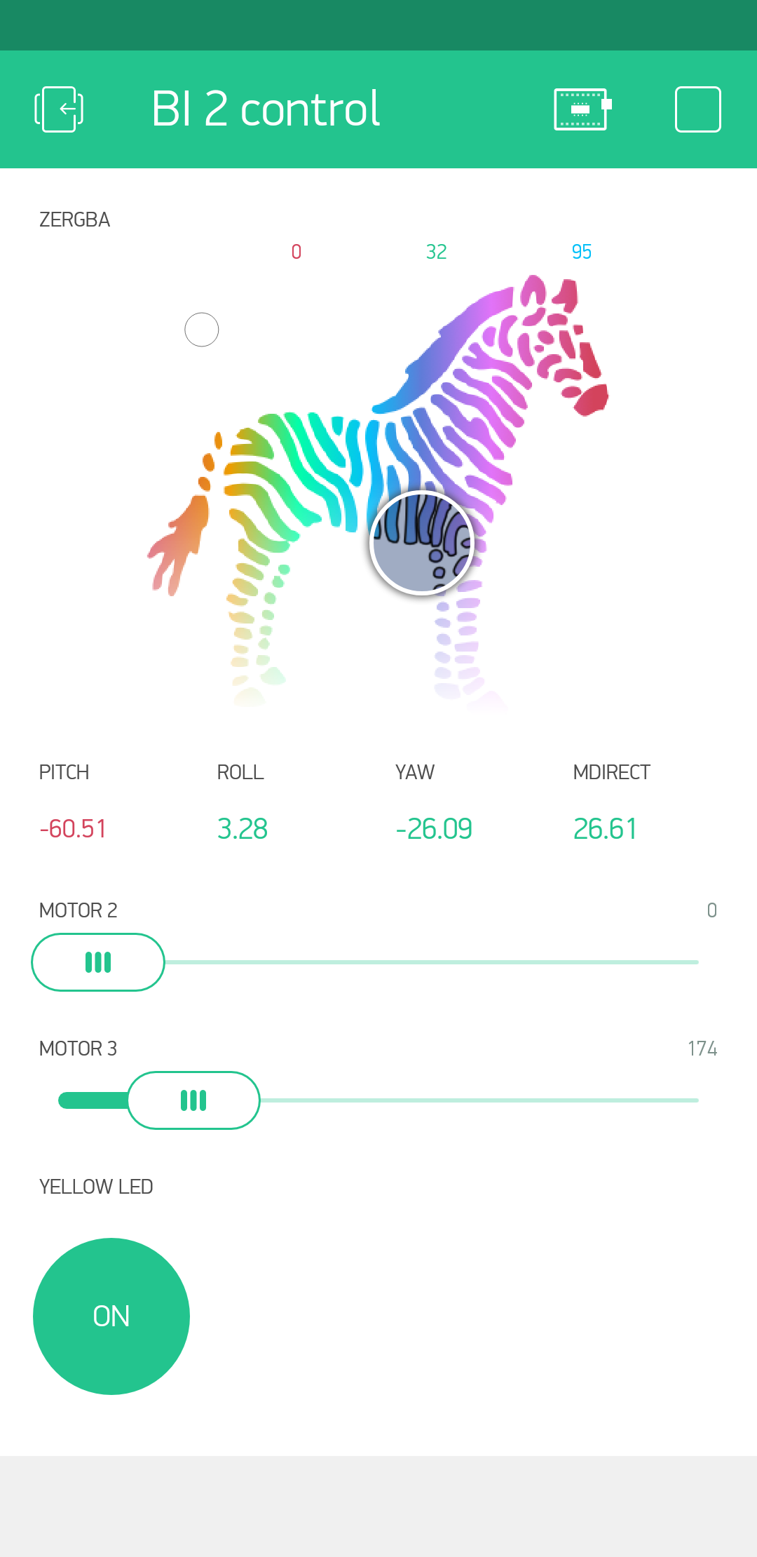
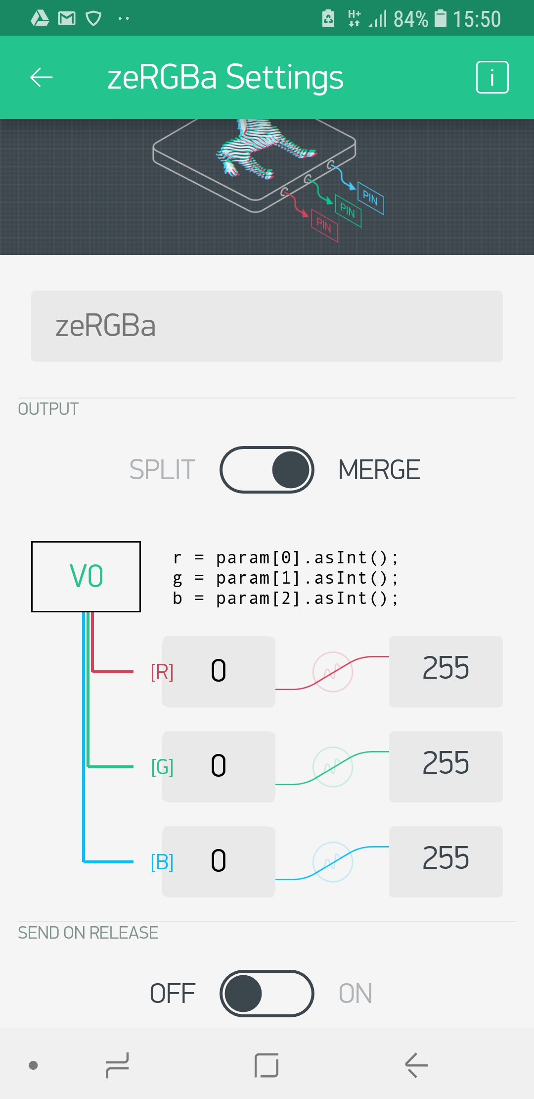 So far communication is only possible with physical pins. But how can you exchange other information? Maybe you want to tell the microcontroller to “shut up immediately”, or you want to play a given vibration pattern like a sinus curve. For this you can use “virtual pins”. (IMHO there is no reason to call this mean of data exchange “virtual” and it is has nothing to do with a pin. You can call it a variable or channel for data exchange.) The zeRGBa widget is a good example. The color of the LED is controlled by 3 values, the amount of red, green and blue color. This 3 values can be connected to one virtual pin (“V0”) and then they will be transmitted to the microcontroller. To change the color of the LED you have to program the microcontroller to read out the amount of each color and set the LED to the appropriate value.
We will demonstrate virtual pins with the LED. The WS2821B LED is connected to pin 14, but you cannot control the LED directly by setting the pin to a given value. This is done by a library which controls the LED.
First we have to include the library, we use FastLED.
#include "FastLED.h"
Then we have to tell how many LEDs we have (you can put several of them in a chain). The BI2 has only one on board (but you can add more).
#define NUM_LEDS 1 // number of LEDs
The you have to tell to which physical pin the LED is connected (14). Finally you have to set up a (instance of an) object “CRGB” for the LED where all relevant data is hidden.
#define DATA_PIN 14 // pin for LED
CRGB leds[NUM_LEDS]; // define the array of leds
Now comes the more difficult part. The zeRGBa widget has 3 values (one for red, one for green, one for blue) and all are put in the virtual variable V0.
We have add a new function called “BLYNK_WRITE(V0)”. To get the first value we have to read out “param[0]”, for the second “param[1]” etc. We want to store this first value in a variable “i” of the type integer. To assure that param[0] is also from the type integer we add “.asInt()”. The value for red is put in variable i, green in j and blue in k.
BLYNK_WRITE(V0) {
  int i = param[0].asInt();
  int j = param[1].asInt();
  int k = param[2].asInt();
}
Now we have to tell the function BLYNK_WRITE what to do with the values i, j an k. This is done by using the method setRGB which is attached to the LED (which is number 0)
leds[0].setRGB(j,i,k);
Now we can make changes to other LEDs (if we have more than one). If you are ready you have to tell the LED to show the new color.
FastLED.show();
In addition a new statement has to be added to setup the LED within the setup part.
void setup() {
  FastLED.addLeds<WS2812B, DATA_PIN, RGB>(leds, NUM_LEDS);
  [...]
Now we can put everything together the script will look like this:
/*************************************************************
Controling the body interaction 2 board with the Blynk app
*/

#define BLYNK_PRINT Serial
#include <ESP8266WiFi.h>
#include <BlynkSimpleEsp8266.h>

// Auth Token infor the Blynk App.
char auth[] = "XXXXXXXXXXXXXXXXXXXXXXXXXXX";

// Your WiFi credentials.
char ssid[] = "XXXXXXXX";
char pass[] = "XXXXXXXX";

// Library for controlling the WS2821B (Neopixel) LED or LED strip
#include "FastLED.h"
#define NUM_LEDS 1 // number of LEDs
#define DATA_PIN 14 // pin for LED
CRGB leds[NUM_LEDS]; // define the array of leds

// This function set the LED color according to the selected RGB values in the app.
// RGB values are controlled in the app with zeRGBa widget
// values are stored in the virtual pin V0
// V0 consists of 3 values for Red, Green, Blue
BLYNK_WRITE(V0) // set LED RGB color values
{
  int i = param[0].asInt();
  int j = param[1].asInt();
  int k = param[2].asInt();
  leds[0].setRGB(j,i,k);
  FastLED.show();
}

void setup()
{
  // init LEDs
  FastLED.addLeds<WS2812B, DATA_PIN, RGB>(leds, NUM_LEDS);

  // connect to Blynk
  Blynk.begin(auth, ssid, pass);
}

void loop()
{
  Blynk.run();
}
Do you like this, do you need this, do you understand this? Tell me jacardano@gmail.com
The new BI2 black vibrator development board
The new black BI2 board is ready. I have a few assembled boards ready for shipping. Have a look at www.tindie.com
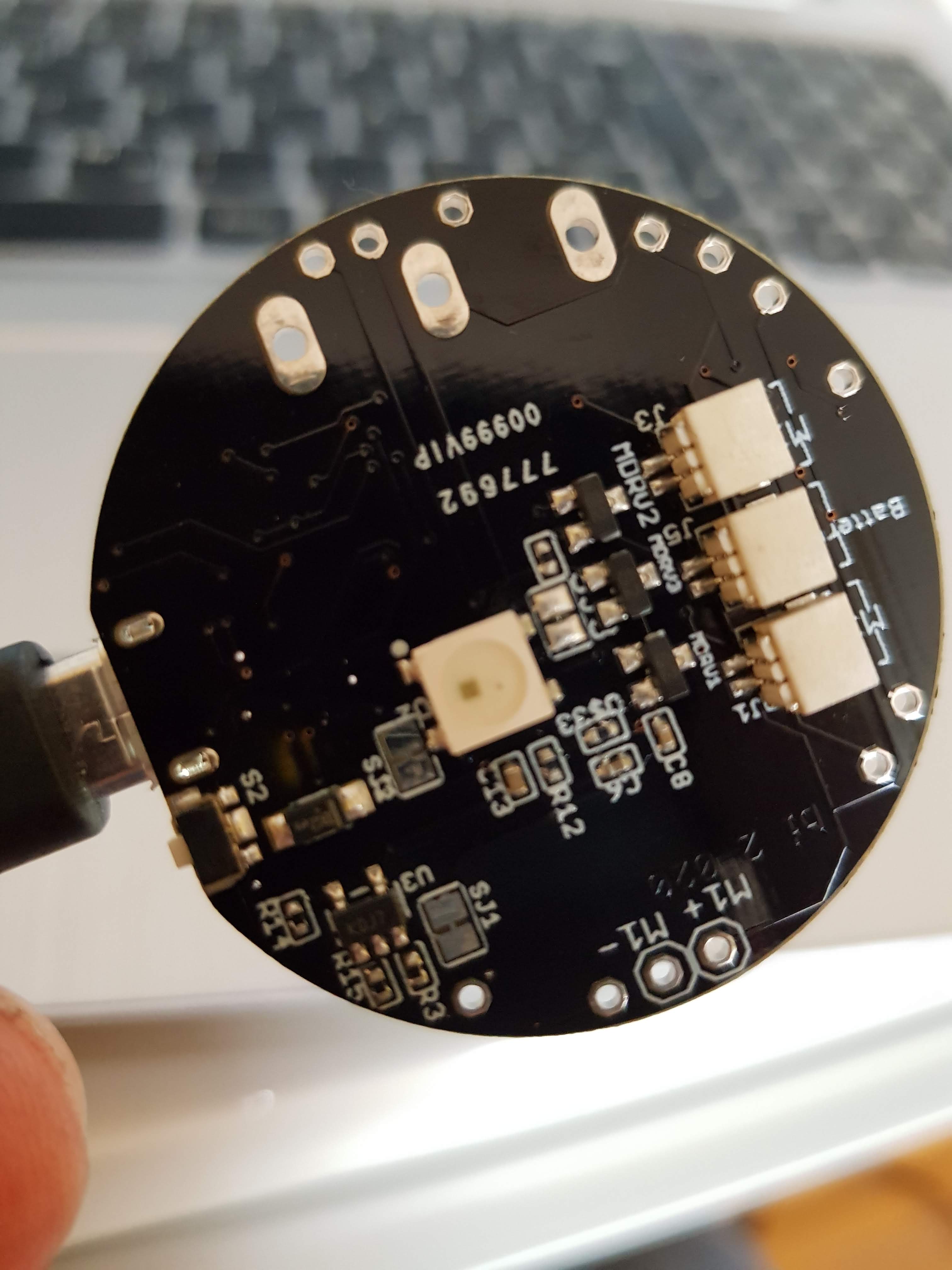
3 JST 1mm plugs (battery, motor 2, motor 3), LED, reset button, M+/M- is for motor 1

JST 1mm plug for motor 1, alternative RESET button
Features
- ESP8266 Microcontroller with WLAN
- MPU9250 (accelerometer, gyroscope)
- LiPo battery charging
- 3 motors can be connected (simple motor driver circuits)
- 1 WS2812B LED – a colourful LED (16 Mill. colours). They are commonly known as Adafruit Neopixel – a strip or a ring of individual programmable LEDs (when use the WS2812B only two motors can be connected)
- design based on the great Adafruit Feather Huzaah ESP8266
- vibration motors and LiPo battery can be easily connected with JST 1mm connectors
- two reset buttons (the button next to the USB connector can be overmolded)
- USB connector for battery charging and code uploading
- programmable with the Arduino IDE or NodeMCU
- white LED for indicating charging
- standard LED (yellow) on GPIO00
- round 40mm diameter

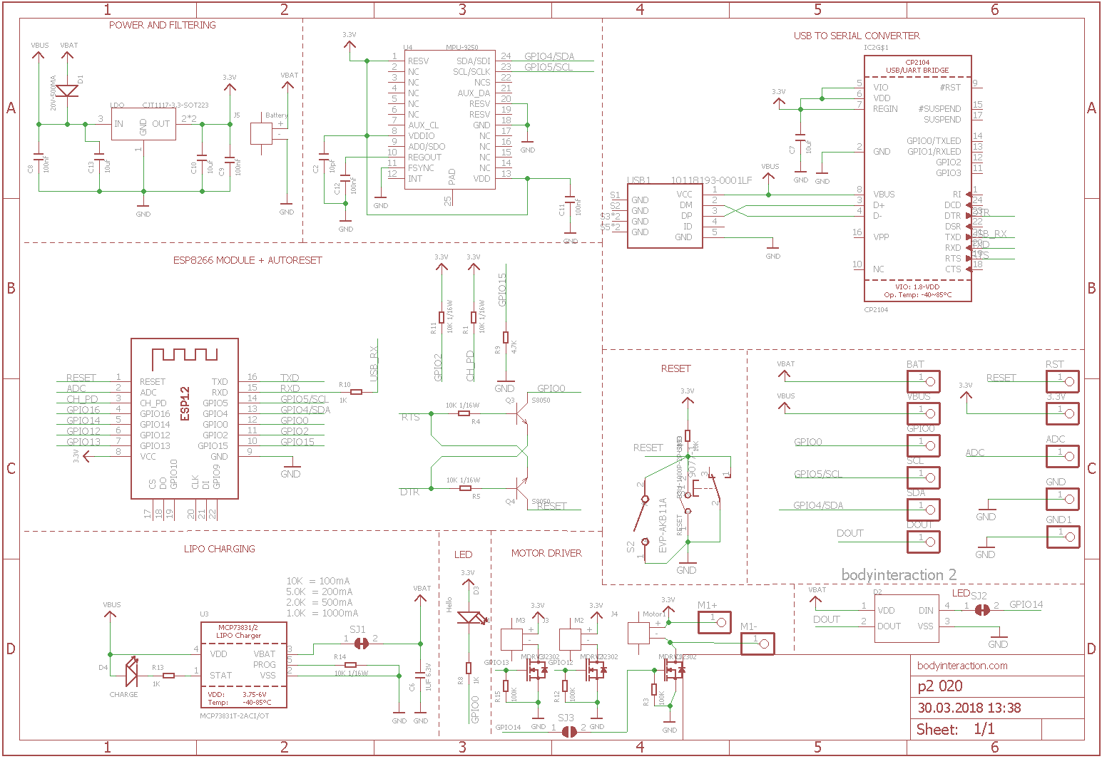
There are 3 free GPIO ports. Standard layout are for driving 2 motors (GPIO 12 = M2, GPIO 13 = M3) and 1 LED (GPIO14). Alternatively you can use 3 motors (GPIO12,13,14) but no LED.
Standard: SJ2 not connected, SJ3 connected
Alternative: SJ2 connected, SJ3 not connected
Here is the schematic which is adapted from Adafruit.
References:

BI2: ESP8266 Vibrator Development Board – becoming colourful
The second version of the development board – I will call it BI2 from now on – has some improvements:
- I used more components of the original design (Adafruit Feather Huzzah) instead of comparable (and cheaper) Seeedstudio Open Part Library components. The reason for this is easy. The Adafruit design is reliable and approved. No need for designing your own circuits, no risk to fail. (But also no fun in inventing new circuits.)
- I added LED light – the WS2812B – which is a colourful LED (16 Mill. colours). They are commonly known as Adafruit Neopixel – a strip or a ring of individual programmable LEDs.
- The diameter is smaller the first version.
- It can drive three motors. (When you use the LED then only two motors can be driven.)
Here are some impressions of the board:


 As you can see I had to wire the LED by hand. The reason for this is that I used GPIO16 which does not work at all. So I wired the LED to GPIO0 which can be used for testing only. The only free GPIOs are 12, 13 and 14.
Making of an ESP8266 Vibrator Development Board – traps and pitfalls
About a year ago I made a ESP8266 based design for a vibrator development board including IMU, motor driver and battery charging. The design was based on the Adafruit ESP Huzaah, but I used components of Seeedstudio Open Parts Library. This is a library of parts (IC, connector, resistors) which are stocked at Seeedstudio especially for their PCBA (printed circuit board assembly) service. PCBA is really great. Instead of tinkering and soldering on your own you can send the design to Seeedstudio, they make the printed circuit board and assemble all parts. Unfortunately the main part – the ESP8266 microcontroller – was missing in the Open Part Library . So I turned to use the affordable ready-made WeMos ESP8266 boards (see here).
In June 2017 I took a closer look at the PCBA service. At that time the OPL offered two variants of the ESP8266. But even better: You could order almost any part. The difference between using OPL parts and other parts was the time for the assembly as it takes more time to order parts which are not on stock.
So I ordered two boards. The boards are round with a diameter of 5 cm (that’s the size of a wireless charging coil). As I had a coupon the two boards were only about 50US$. Including delivery! And even better: Seeedstudio delivers from a logistic company in Germany. So I had not to pay any taxes. Great. But… unfortunately … I made beginner’s mistakes…during design.

- Problem: As the board should be programmable by USB connection you need a USB to serial bridge eg. one of the FTDI ICs. This bridge has two important connections TX (transfer) and RX (receive). And the ESP8266 has the same TX and RX. But don’t connect them. Instead you have to connect RX to TX and vice versa. (Well I should have know, when I soldered null modems maybe 20 years ago or more…)
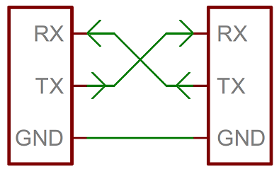
Taken from Sparkfun
- Problem: When using the serial monitor of the Arduino IDE you need another connection: RTS (ready to send). Unfortunately the used serial bridge – the FTDI FX230XS IC – had no RTS. (There is a circuit which works without RTS, but I didn’t know.)
- Problem: I used GPIO0 for driving the motor, that’s why auto reset doesn’t work. So I had to short-cut GPIO0 and GROUND for uploading a script.
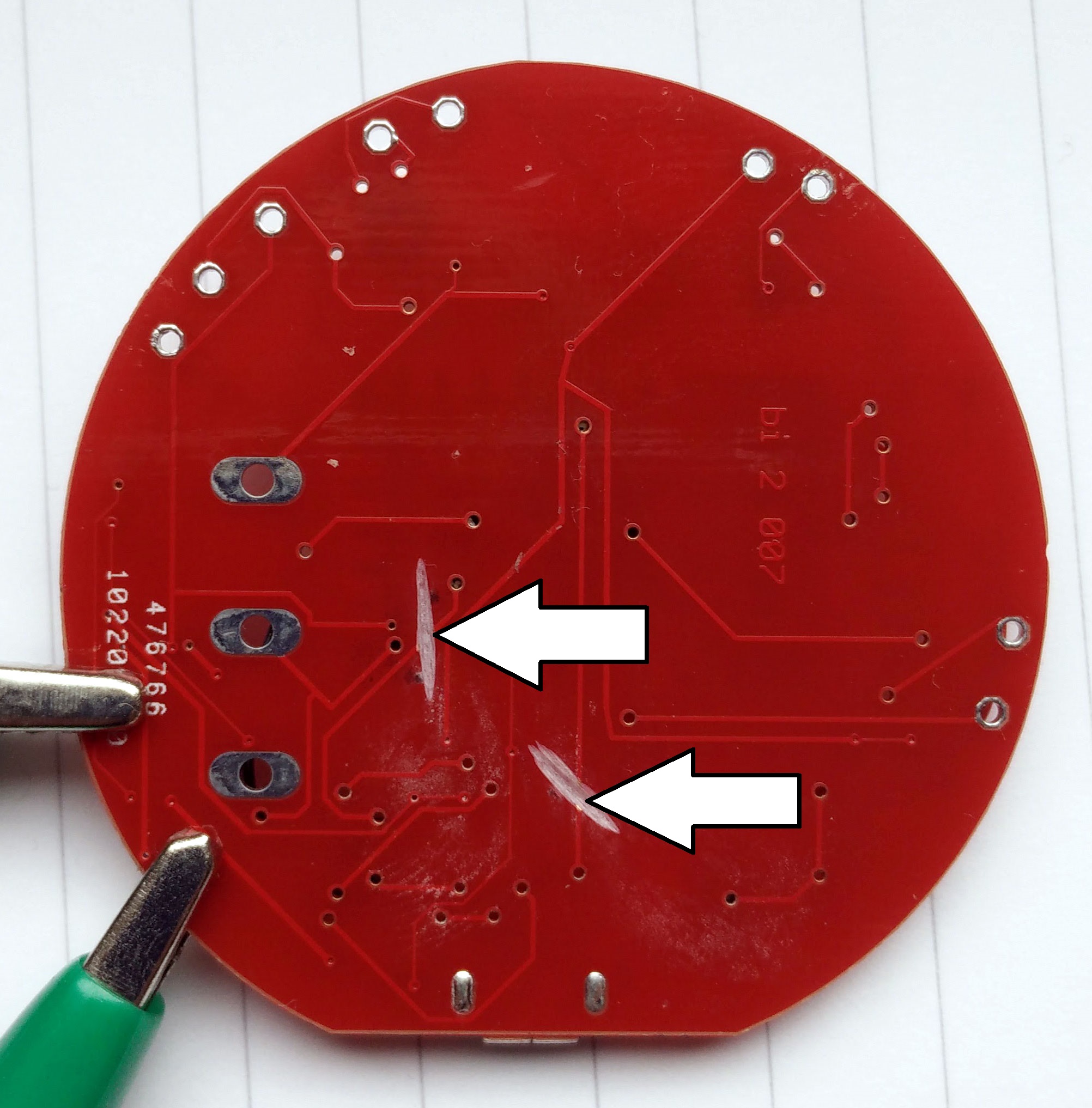
So I tried to fix the problem. At first I had to cut the wrong connections. On the bottom side of the board the RX and TX wires are quit good accessible. So I could cut them using a dremel.
In the next step I had to connect the RX and TX headers of the FTDI chip with the ESP 8266…
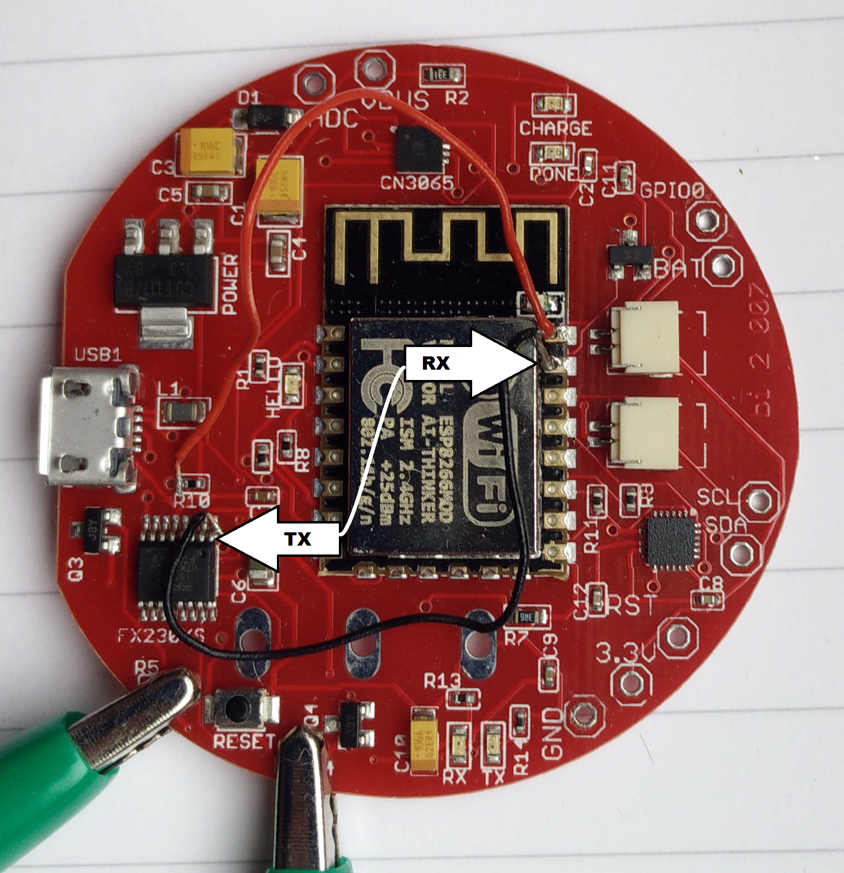
The green clamps were used to shortcut another wrong connection.
Finally upload with the Arduino IDE was possible, but no debugging using the serial monitor. Battery charging seemed to work, too, although this needs more time for testing. WiFi worked. Essentially I could upload a script which made one LED blinking. And I could start the WiFi manager.
Debugging such a complex thing like a ESP8266 without serial connection is almost impossible. But then I found RealTerm. This is the only terminal program for Windows where you have all options to use or not use serial sync mechanisms like DTR, RTS etc. It is made to make a serial connection work even if you have only TX, RX and GROUND.
Here you can decide to ignore RTS and/or DTR by pressing “Clear”. (Read more about this here.)
.![]()
And finally it worked. The ESP8266 sends debug text to the serial monitor. The transmission maybe scrambled, but it is still readable. Realterm – a really great tool for debugging serial connections.

Readings of the MPU9250 (accelerometer, gyro)
Probably it is more reasonable to use a bread board for the development of a design. But customizing an open source design on the PC and then get it assembled for a reasonable price – for me it’s like a dream come true. But as you see – all your efforts can be worthless.
 But I will do it again…
Basic Node for the Internet of Sex Toys – part 3: software
This the third part of the tutorial which has the following parts:
part 1: Basic Node for the Internet of Sex Toys
part 2: Molding the Basic Node
part 3: Software for the Basic Node
For the basic node a simple software realizes all features like Mqtt communication, Web server, basic web user interface, reading data from the accelerometer. Please use the code at github and send request over github. Now the imported parts of the code are explained.
To communicate with the IOT Mqtt is used (read more here). This is a fast protocol for data transmission. Therefore we need a Mqtt server. You can install one on your local computer or use a cloud-based Mqtt server. We use the free CloudMqtt. The following variables must be initiated with the data of your server. Please get your own account at CloudMqtt or use my server (but don’t spam it, please). Please remember: Transmission is not encrypted, everybody can read it.
const char* mqtt_server = "m12.cloudmqtt.com";
uint16_t mqtt_port = 15376;
const char* mqtt_user = "nvcuumkf";
const char* mqtt_password = "C-X6glwisHOP";
We have now 7 different modes. In each mode the basic node behaves different.
const int offMode = 0;
const int maxMode = 1;
const int sinusMode = 2;
const int motionMode = 3;
const int constantMode = 4;
const int listenMode = 5;
const int listenAndMotionMode = 6;
In off mode the basic node is off, in max mode the vibration is maximum. In sinus mode the vibration speed is altered according to a sinus curve.

Web user interface of the basic node
In motion mode the vibration changes according to the movement of the basic node. When moved fast the speed goes up, when moved slowly or movement stops, the speed goes down. In constant mode any vibration speed can be set to any strength. This feature is only available by Mqtt messages eg. from the IOT node-RED user interface. The listen mode is still experimental. In this mode the speed will be changed by OTHER basic nodes. Finally in the listenAndMotionMode the speed is changed by movements of the basic node and by other nodes. This feature was already available with the body interaction 1 development board as standard mode!
The basic node starts a web server (see image). A web page is generated which build up the user interface. There are buttons for every mode. In addition the speed and the battery power is displayed. This is done in this function:
void generateWebpage() {
The next lengthy procedure is this:
void mqttCallback(char* topic, byte* payload, unsigned int length) {
This is a call back function which is executed whenever a Mqtt message comes in. It parses the Mqtt message which is in the popular JSON format. The commands which are communicated within JSON are explained here. In principle there is a command for every mode, when the command “set mode to off” is send the mode is set to offMode.
In the setup() part of the code you will find a lot of lines like that:
httpServer.on("/MOTOR=MAX", []() {
They corresponds to the generateWebpage() function. When say the max button on the web page is pressed than the affiliated httpServer function is executed. So for every button on the webpage you need a corresponding httpServer function to implement the functionality. In this case (MOTOR=MAX) the mode is set to the constant speed maxMode.
Finally in the loop section of the code the following functions are implemented:
- reading the accelerometer data
- change the vibration motor speed according to the mode
- generate a new JSON message which is send out via Mqtt
- do the timing
Not mentioned is the OTA (over the air update) function, which is integrated in the code.
Node-RED
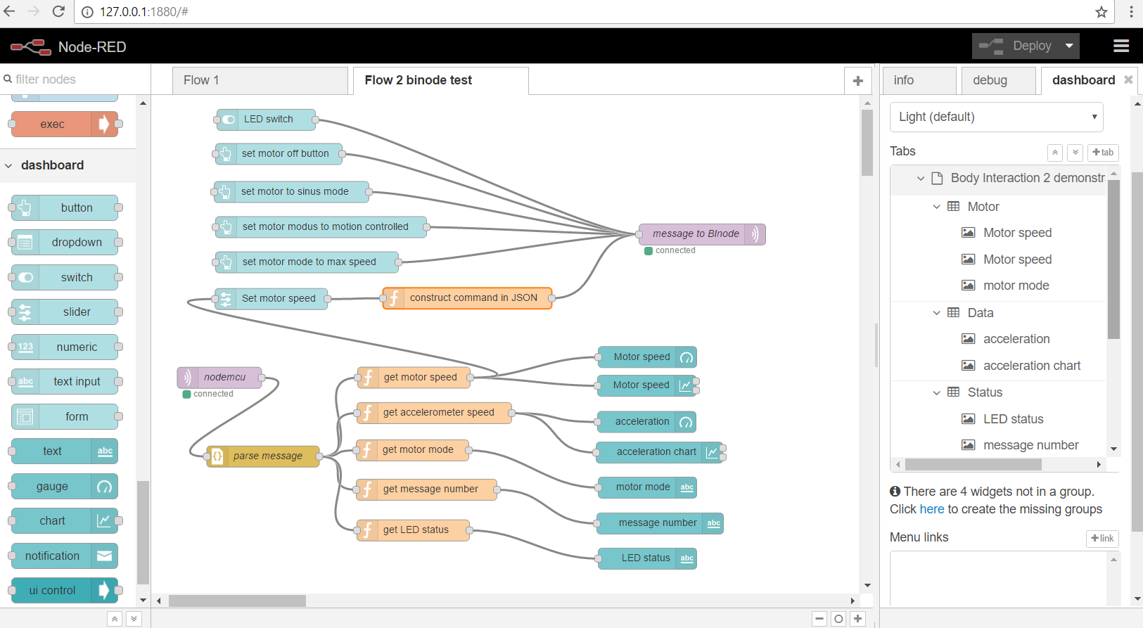 For controlling the toy via the internet you can use node-Red. You can find the code at github via this link.
The flow is explained here and here.
Basic Node for the Internet of Sex Toys (part 1)

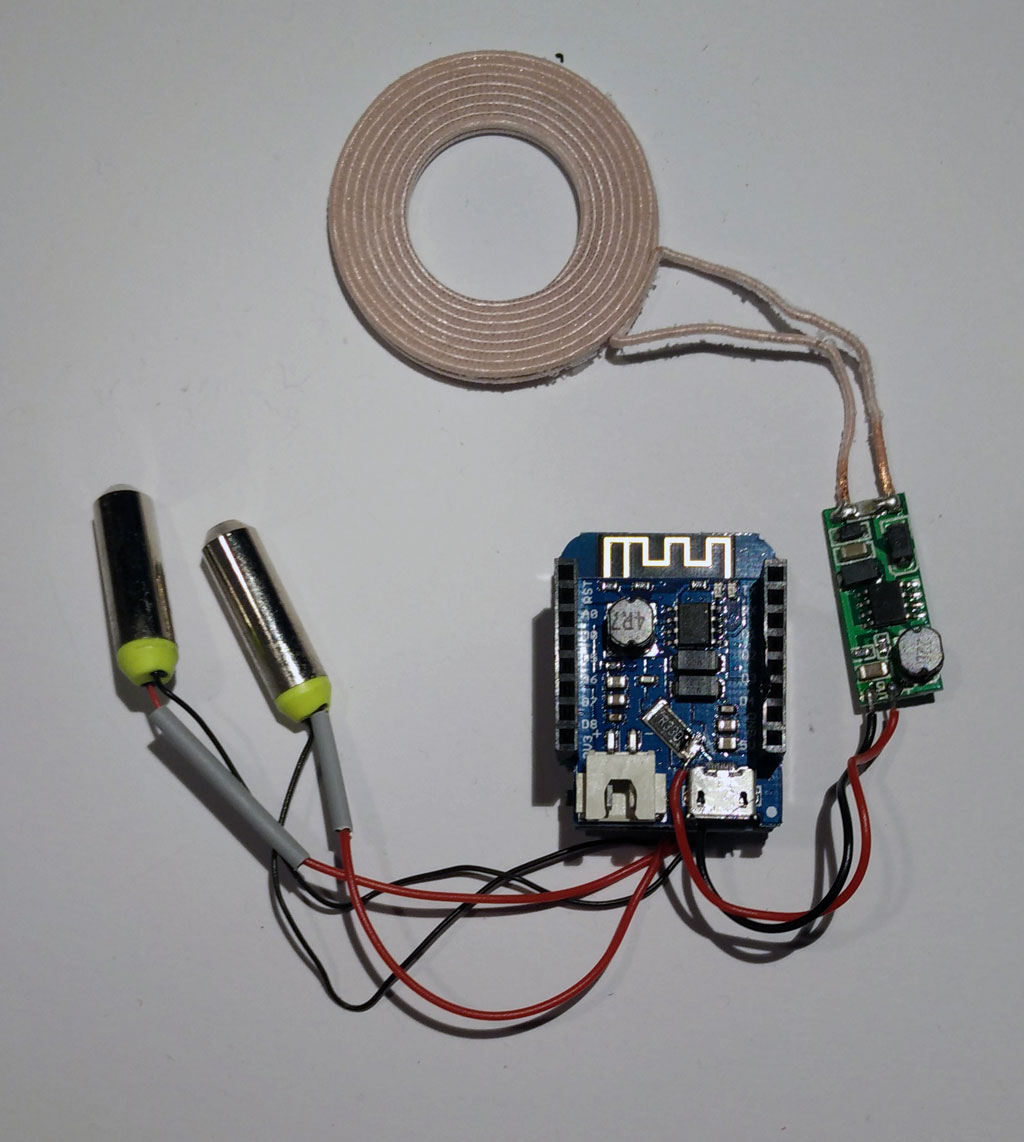
Wemos mini modules: ESP8266, motor driver and battery charging (in the middle); Wireless charging module (right side); wireless charging coil (top side); encapsulated vibration motors (left side)
In previous posts we showed how to build a vibrating sex toy in principle as part of the Internet of Things (IOT). In addition we have selected a hardware platform – the popular ESP8266 – for controlling a vibrator motor, gathering motion data and connecting to the internet. Now we want to build the toy itself.
part 1: Basic Node for the Internet of Sex Toys
part 2: Molding the Basic Node
part 3: Software for the Basic Node
Brief Review of development boards
There are a lot of development boards which are equipped with the ESP8266. The popular NodeMCU was already introduced here. Here is a quick overview and comparison:
- plus: very popular, cheap, USB connector for programming
- minus: quite large (for being part of a sex toy), no support for battery charging
- plus: USB connector for programming and battery charging, smart form factor (only 23 mm wide), very good support (libraries, tutorials)
- minus: quite expensive
- plus: very cheap, USB connector for programming, additional stackable modules (eg. battery charging, TFT screens, motor driver), good form factor
- minus: no real support (but there is a forum, problems with modules reported
ESP8285 (variant of the ESP8266)
- plus: really small (!!!) and smart form factor, USB programming and battery charging, optional sensors on board (but no motion sensors)
- minus: quite expensive, only 1MB memory (nevertheless enough for a lot of application)
For our project we selected the WeMos mini cause we get almost everything we need:
- USB connector for programming
- module for battery charging
- module for a motor driver
- good form factor (eg. to be put in a vibrator handle or in the base of a dildo)
- cheap, fast delivery
But there is no shield for motion detection (accelerometer,gyroscope). So we have to use an additional board eg equipped with the MPU9250.
But there is a problem with the WeMos motor shield: After a few seconds it stopped working. And in addition the MPU9250 stopped working, too. Hours and hours we tried different configurations, changed the libraries … The problem was the motor driver shield itself. Fortunately there is an easy work around. Read here.
Another issue is the battery shield. It has an extra USB connector for charging the battery. So you have two USB connectors (one for battery charging and one for uploading). Two USB connectors are not handy. Fortunately we can do without the USB connector for uploading as it is possible to update the software over the air (OTA) using WiFi.
Material
As the body interaction philosophy uses motion for controlling the device we have to add the MPU. Again we use the MPU9250 which has an accelerometer, gyroscope and magnetometer.
Another insight was that you need at least a switch for rebooting. As we want to mold everything the switch must meet the IP67 requirements, which means it is water- (and silicone) proof. If you don’t want to mold the electronics you can use the RESET button on the WeMos mini board.
A perfect basic node has a wireless charging option, too.
Material list for the basic node:
- Wemos mini board
- Wemos motor driver shield
- Wemos battery shield
- Wemos prototyping board
- Wemos set of pins
- LiPo battery (eg. 3,7V 650mAh, 2C, JST plug, available at ebay)
- MPU 9250 board (for motion control)
- 1 or 2 encapsulated vibration motors, 3V, available at Alibabaexpress
- Optional: Switch IP 67 protected (eg. Cherry Switches DC1C-K8AA IP67) – for molding
- Optional: Wireless charging receiver 5V eg from Seeed Studio

Material: battery shield, Wemos mini ESP8266, motor shield, MCU9250 (first row), LiPo battery, switch, vibration motor (second row)
Soldering the basic node
We use one connector (part of the Wemos set of pins) to connect the Wemos mini with the battery shield and the motor shield. This is done to save space. If your application has enough space you would use one connector for every shield.
Battery shield, Wemos mini ESP 8266, motor shield (from top to bottom)
Now have a look at the bottom side where the motor shield should be. We can connect up to 2 motors. Solder motor 1 to A1 and A2. Motor 2 has to be soldered to B1 and B2. In addition we need input power for the motor. We just use the 5V provided by the Wemos mini battery shield. Connect 5V to VM and GND (from the pins) and GND. But you could use other (more powerful) power sources, too.
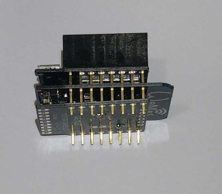
 Wemos offers a prototyping board. We use it for mounting the switch and for the MPU9250. Connect the MPU9250 to the bottom side of the prototyping board. Therefore 4 pins have to be soldered

Solder pin (1 row, 4 pins) on the top side next to TX, RX, D1, D2
Now look at the bottom side of the prototyping board. Put the MPU 9250 so that VCC, GND, SDA, SCL are connected to the pins.
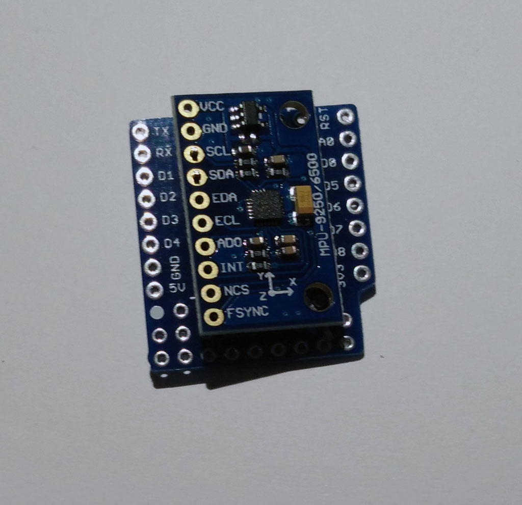
Next, solder the MPU 9250.
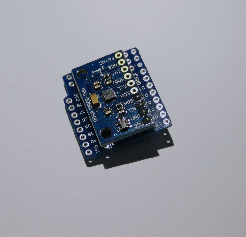 Then add more pins to the prototyping board at both sides. The picture shows the bottom side of the prototyping board.
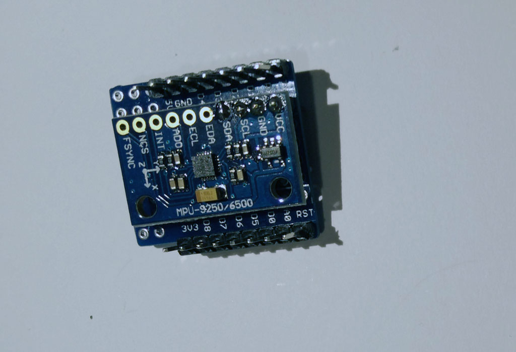
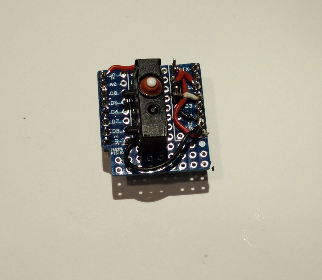
Now wire the prototyping board. The picture shows the top side.
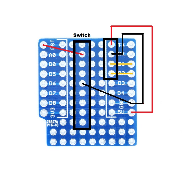
Now you can add the switch. Place it in the middle of the board on the top side. Connect GND and RST to the switch. Now you have a switch for rebooting which can be molded.
 Now we have both parts ready and can stack them together.
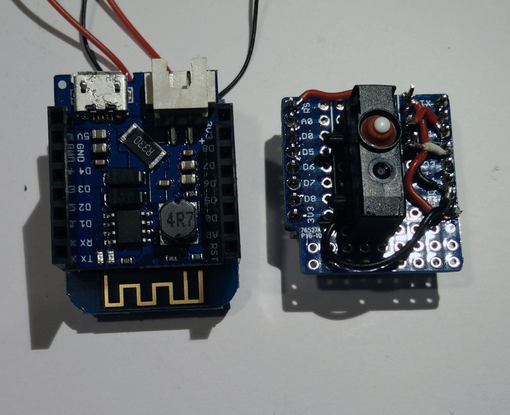 Stack them together!
 Now add the LiPo battery, which should have a JST header. Now your basic node is ready.
Wireless charging option
Especially for sex toys a wireless charging option is reasonable as this is a requirement for silicone molding of the toy. And when the toy is molded it is safe and washable.
The wireless charging module consists of a sender (or transmitter module) and a receiver module. You have to solder the receiver module to the battery shield. Don’t mix the modules.
unfortunately there is only a USB connector. If you don’t want to remove the USB connector you can solder the red (+) wire to the R330 resistor as shown on the pictures. The black (-) wire can be soldered to any pin labeled (GND).

Now put the receiver module on top of the battery module.
 Now stack the protoytping board on top of the battery shield. And connect the battery.
 To charge the battery connect the sender (or transmitter) module to 5V. To power the sender module you may use a USB port power source which has about 500mAh or more. Place sender and receiver coil about each other. For a more professional charging solution you need a charging station. The making of a charging station using 3d printing is described here.
Learn how to construct the mold form in part 2:
part 2: Molding the basic node
part 3: Software for the basic node
More Sex Tech Projects
 There are at least a few (new) open source or DIY projects. Future of Sex reported about a Strap-on project named Dildo It Yourself.
They created a website for sharing designs for strap-on dildos. In addition the strap-on dildos is part of a harness. Some parts can be 3d printed but the harness must be made by leather or other material which could be out of scope for most DIY people. The inventors say that their toys are made for ecosexuals which practise sex in nature.
 Another project is very impressive as it offers a touch surface for a “insertible toy” eg a penis. This could be used for teledildonics application for capturing and transmitting haptical experience. The construction of the capacitive surface is very impressive. In addition algorithms are introduced for gesture recognition. Gestures? The author explains: “Well, I want to be able to tell what the user is doing with the device (e.g. blowjob, licking, hand job and penetrative buttsex)”.
Another exciting project is a masturbator demonstrator which was molded using 3d printed forms.
 Finally there is a very interesting website from the “mad scientist” Franklin. He has made a lot of stuff like a gesture controlled vibrator, a brain controlled vibrator and a Bionic cock.
For commercialisation a Company Tacit pleasure was found. That was back in 2014, but the work is still interesting.
Although these projects are very different in aspects like audience, technical elaborateness and motivation they show the richness of sex tech projects.
OpenSCAD as silicone molding form generator
 An alternative to 3d-printed sex toys are silicone toys. For making such a sex toy you need a molding form, where you pour in the silicone. If you use Tinkercad to build the form for the balls motive, you may need more than one hour. If you are not experienced in 3d constrcution it may take days. That’s ok and can be fun as you can realize your fantasies step by step.
 But if you want to change a detail or want to resize some parts of it, it will take a long time as you have to unbuilt parts of the form, make changes and then reassemble. Sometimes building from scratch is faster.
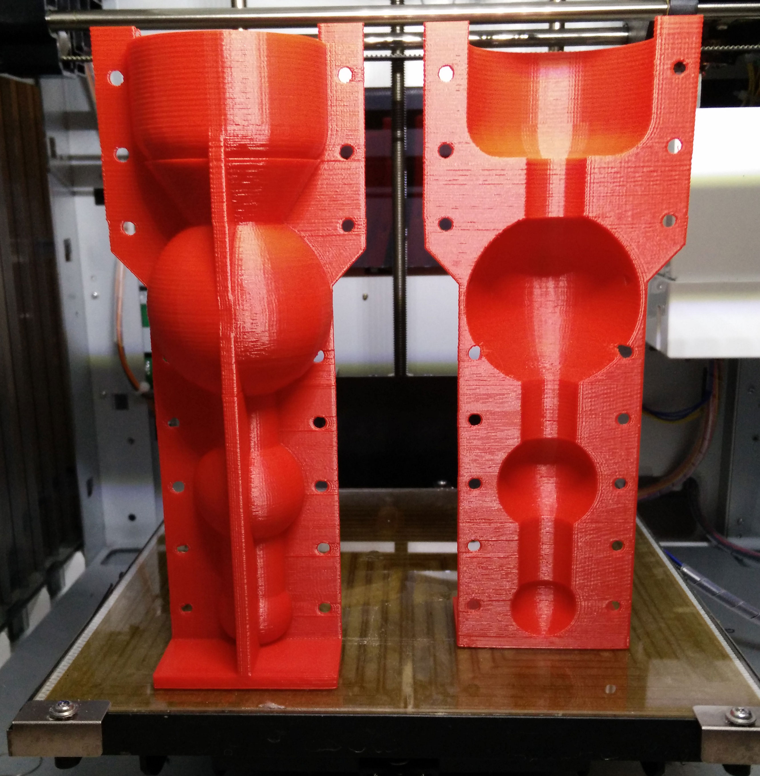
In the last blog post we have introduced OpenSCAD to construct a sex toy form. Now we want to build a hull for the sex toy for overmolding.
The basic idea is very simple:
- Generate two forms. The smaller one has the size of the sex toy you want to make. The larger one will be the form where you pour in the silicone.
- Than use the OpenSCAD difference command which “subtracts” or cuts out the smaller form from the larger form.
But it is more complicated:
- You have to include a frame otherwise the form would fall over.
- You need two forms (A and b) so you could open the form after molding.
- Both forms must be fastened together when molding. Therefore you need holes for tinkering wire.
 We have created a solution for molding form generation which is as flexible as our OpenSCAD sex toy generator. In addition you can change the thickness of the frame. Therefore you have to change the variable frame_thickness.
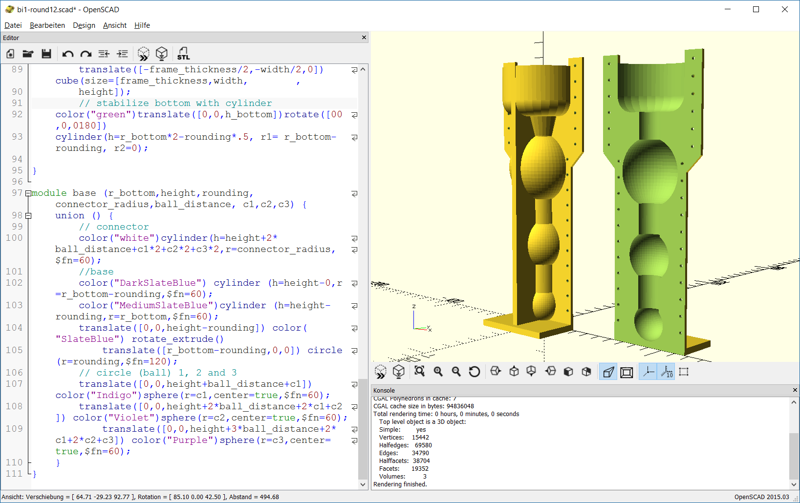
The SCAD script uses the module base which is already introduced. The generation of the frame is done in the module frame. The frame consists of a base plate and two supporting frames which stabilize the whole form. In addition there are extensions to the frame in the upper part of the form. These extensions will provide holes for fastening both forms.
The module complete_form constructs the form which is tricky. The union command is used to join the complete outer form and the frame. Now we have a filled form and have to remove the inner part. This is done by subtracting another complete form which is a bit smaller than the outer form. This is done with the difference command.
Another module hole provides all holes for the tinkering wire. At last we construct part A and part B of the molding form. Again the difference command is used to cut out one half of the form. This is done by subtracting a cube which is placed in the middle of the complete form. In addition the holes must be subtracted from the complete form.
 You can build in the body interaction vibrator development board to make a vibrating dildo, controlled by motion or by another body interaction vibrator development board. Read more here.
Try out with the Thingiverse customizer.
Download the zipped SCAD file here: bi1-round12
Or copy and paste the source code to the SCAD software:
// bodyinteraction toy form and mold form generator
// radius of bottom part
r_bottom=25; // [15:5:80]
// height of bottom part
h_bottom=30; // [10:5:80]
// top rounding of bottom part
rounding=10; // [10:5:20]
// radius of ball 1
r_ball1=21; // [15:5:50]
// radius of ball 2
r_ball2=15; // [15:5:50]
//radius of ball 3
r_ball3=11; // [15:5:50]
// radius of connecting cylinders
connector_radius=8; // [10:2:20]
// distance between balls and bottom part
ball_distance=15; // [10:2:40]
// offset (thickness of hull)
o=2;
// thickness of frame
frame_thickness=4;

height=h_bottom+3*ball_distance+r_ball1*2+r_ball2*2+r_ball3*2; echo(height);


// form part A
translate([0,0,height+frame_thickness])rotate([0,180,0])
difference() {
 complete_form(r_bottom,h_bottom,rounding,r_ball1,r_ball2,r_ball3,connector_radius,ball_distance,o,frame_thickness,height);
union(){
 translate([-r_bottom-o-10,0,-5])
 color("red")cube([2*r_bottom+2*o+20,r_bottom+2*o,height+frame_thickness+5]);
 holes(height,h_bottom);
 }
}
//form part B
translate([90,0,height+frame_thickness])rotate([0,180,0])
difference() {
 complete_form(r_bottom,h_bottom,rounding,r_ball1,r_ball2,r_ball3,connector_radius,ball_distance,o,frame_thickness,height);
union(){
 translate([-r_bottom-o-10,-r_bottom-o-2-10,-5])
 color("red")cube([2*r_bottom+2*o+20,r_bottom+2*o+10,height+frame_thickness+5]);
 holes(height,h_bottom);
 }
}

module holes (height,h_bottom){
for (i=[h_bottom+30:10:height])
 translate([r_bottom-1,5,i])rotate([90,90,0])
 color("green")cylinder(h=15,r=1,$fn=20);

for (i=[0:10:h_bottom+20])
 translate([r_bottom-3+10,5,i])rotate([90,90,0])
 color("blue")cylinder(h=15,r=1,$fn=20);

for (i=[h_bottom+30:10:height])
 translate([-r_bottom+1,5,i])rotate([90,90,0])
 color("green")cylinder(h=15,r=1,$fn=20);
for (i=[0:10:h_bottom+20])
 translate([-r_bottom-6,5,i])rotate([90,90,0])
 color("blue")cylinder(h=15,r=1,$fn=20);
}

module complete_form (r_bottom,h_bottom,rounding,r_ball1,r_ball2,r_ball3,connector_radius,ball_distance,o,frame_thickness,height) {
 difference() {
 union() {
 base(r_bottom+o,h_bottom+o,rounding,connector_radius+o,ball_distance-2*o,r_ball1+o,r_ball2+o,r_ball3+o);
 //complete frame
 frame(2*r_bottom+2*o,o,height,frame_thickness,r_bottom,h_bottom,rounding);
 };
 base(r_bottom,h_bottom,rounding,connector_radius,ball_distance,r_ball1,r_ball2,r_ball3);


};
}

module frame(width,o,height,frame_thickness,r_bottom,h_bottom,rounding) {
 //plate
 translate([-width/2,-width/2-2*o,height]) cube(size=[width,width+2*o,frame_thickness]);
 //frame1
 translate([-width/2,-frame_thickness/2,0]) cube(size=[width,frame_thickness,height]);
 //frame 1 extensions
 translate([-width/2-010,-frame_thickness/2,-5]) color("blue")cube(size=[12,frame_thickness,60]);
 translate([-width/2-10,-frame_thickness/2,55]) color("red")rotate([0,45,0]) cube(size=[12,frame_thickness,20]);

 translate([+width/2-2,-frame_thickness/2,-5]) color("green")cube(size=[12,frame_thickness,60]);
 translate([+width/2+01,-frame_thickness/2,47]) color("green")rotate([0,-45,0]) cube(size=[12,frame_thickness,20]);
 //frame2
 translate([-frame_thickness/2,-width/2,0]) cube(size=[frame_thickness,width, ,
 height]);
 // stabilize bottom with cylinder
 color("green")translate([0,0,h_bottom])rotate([00,0,0180])
 cylinder(h=r_bottom*2-rounding*.5, r1= r_bottom-rounding, r2=0);

}

module base (r_bottom,height,rounding,connector_radius,ball_distance, c1,c2,c3) {
 union () {
 // connector
 color("white")cylinder(h=height+2*ball_distance+c1*2+c2*2+c3*2,r=connector_radius,$fn=60);
 //base
 color("DarkSlateBlue") cylinder (h=height-0,r=r_bottom-rounding,$fn=60);
 color("MediumSlateBlue")cylinder (h=height-rounding,r=r_bottom,$fn=60);
 translate([0,0,height-rounding]) color("SlateBlue") rotate_extrude()
 translate([r_bottom-rounding,0,0]) circle(r=rounding,$fn=120);
 // circle (ball) 1, 2 and 3
 translate([0,0,height+ball_distance+c1]) color("Indigo")sphere(r=c1,center=true,$fn=60);
 translate([0,0,height+2*ball_distance+2*c1+c2]) color("Violet")sphere(r=c2,center=true,$fn=60);
 translate([0,0,height+3*ball_distance+2*c1+2*c2+c3]) color("Purple")sphere(r=c3,center=true,$fn=60);
 }
}
Go to the first part of the SCAD tutorial
OpenSCAD as sex toy generator
 OpenSCAD is a free software tool for creating 3d objects. But it is different from other CAD tools like Tinkercad or Freecad. Instead of using the mouse to select and modify 3d objects you have to use a description language. Making a 3d object in OpenSCAD is a bit like programming. For creating a sphere you just have to type sphere(r=10); where r is the radius of the sphere. For creating a cube or a cylinder just type in the appropriate command. When done select compile from the menu and you’re object will be displayed.
Just download the OpenSCAD software, install the tool and try out a command. You can copy and paste the dildo generator source code (at the end of this blog post) and try to change the parameters. Another option is to use the customizer module of the Thingiverse platform.
Brief Intro to OpenSCAD
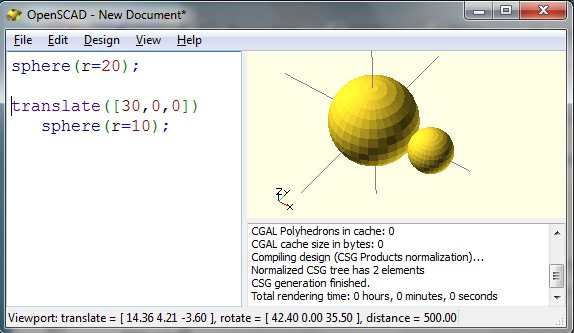 If you want to create a sphere not in the origin but somewhere else you have to shift the object using the translate command. For creating the second smaller sphere use
translate([30,0,0]) sphere(r=10);
The translate command moves the sphere objects on the x-axis by 30 points.
To visualize the form use the design menu and select “compile” or “compile and render”. Rendering takes some time (up to some minutes) but it will give you a correct preview of your form.
To build more complex objects you have to use the union or difference command. The union command puts simple objects together. With the difference command you can cut out something e.g. to make a ring. 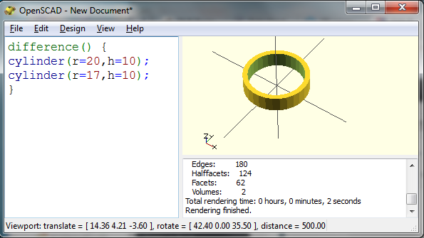 You can download a STL-file (select “export STL” from the menu) and print out the form with a 3d printer.
OpenScad can be used to create sex toys as shown by Mr O. He used OpenScad to create basic building blocks for sex toys which can be combined and changed in size. Moreover with OpenScad you can make generative designs. For example you can make a generative dildo which can be individualized by changing parameters like height, length etc.
Generative Dildo Project
Let us create the “balls” dildo which is introduced in Silicone overmolded vibrator – balls revisited and Update for “balls revisted” – silicone molded vibrator.
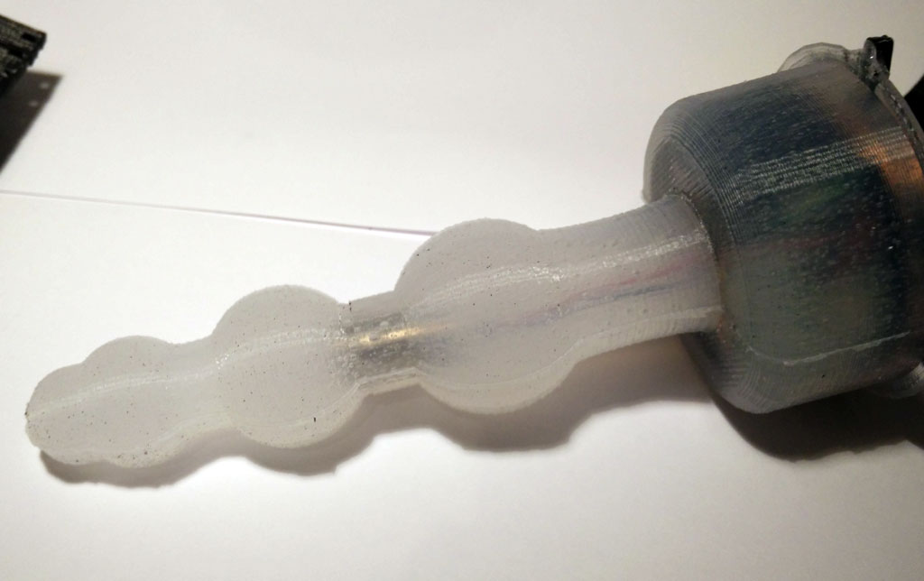 The dildo consists of 6 forms:
- three spheres with individual radius
- a base which is made of cylinders
- and an iterative use of circles to make the upper top of the base to be round
We use the module command to encapsulate the commands for creating the dildo. A module is very similar to functions or procedures in other programming languages, but they do not return a value. They just execute the commands in the module. The definition of the module starts with its parameters.
module base (r_bottom,height,rounding,connector_radius,ball_distance, c1,c2,c3) {
  ...commands for creating the dildo...
}
c1, c2 and c3 are the radius of the spheres. r_bottom is the radius of the base part and height the height if the base parts.
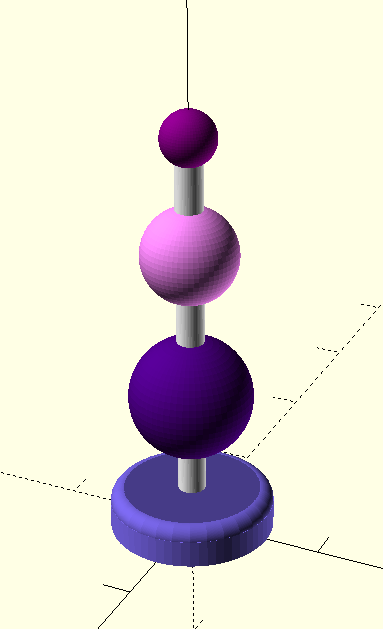
Now you can produce different versions of the ball motive by entering different parameters when you call the module base. With the following parameters the form at the left side will be generated:
base(50,60,10,10,30,15,25,35);
 This form will be made when using the following parameters:
base(60,30,10,10,30,20,35,45);
Make your own generative sex toy design and publish it
The Thingiverse platform is able to create objects made with OpenSCAD. Just upload the SCAD-file to Thingiverse using the customizer option. Now you can change the parameters within Thingiverse and generate a customized STL-file for 3d printing. Try it out with the Thingiverse customizer (as long as nobody complains…).
Download the SCAD file source code here: form_only
Or copy & paste the following SCAD code to generate the “balls” sex toy:
// bodyinteraction toy form

// radius of bottom part
r_bottom=50; // [50:5:80]
// height of bottom part
h_bottom=60; // [10:5:80]
// top rounding of bottom part
rounding=10; // [10:5:20]
// radius of ball 1
r_ball1=35; // [15:5:50]
// radius of ball 2
r_ball2=25; // [15:5:50]
//radius of ball 3
r_ball3=20; // [15:5:50]
// radius of connecting cylinders
connector_radius=10; // [10:2:20]
// distance between balls and bottom part
ball_distance=30; // [10:2:40]


base(r_bottom,h_bottom,rounding,connector_radius,ball_distance,r_ball1,r_ball2,r_ball3);

module base (r_bottom,height,rounding,connector_radius,ball_distance, c1,c2,c3) {
 union () {
 // connector
 color("white")cylinder(h=height+2*ball_distance+c1*2+c2*2+c3*2,r=connector_radius,$fn=60);
 //base
 color("DarkSlateBlue") cylinder (h=height-0,r=r_bottom-rounding,$fn=60);
 color("MediumSlateBlue")cylinder (h=height-rounding,r=r_bottom,$fn=60);
 translate([0,0,height-rounding]) color("SlateBlue") rotate_extrude()
 translate([r_bottom-rounding,0,0]) circle(r=rounding,$fn=120);
 // circle (ball) 1, 2 and 3
 translate([0,0,height+ball_distance+c1]) color("Indigo")sphere(r=c1,center=true,$fn=60);
 translate([0,0,height+2*ball_distance+2*c1+c2]) color("Violet")sphere(r=c2,center=true,$fn=60);
 translate([0,0,height+3*ball_distance+2*c1+2*c2+c3]) color("Purple")sphere(r=c3,center=true,$fn=60);
 }
}
