Tag: vibrator

BI2 – building a silicone sex toy

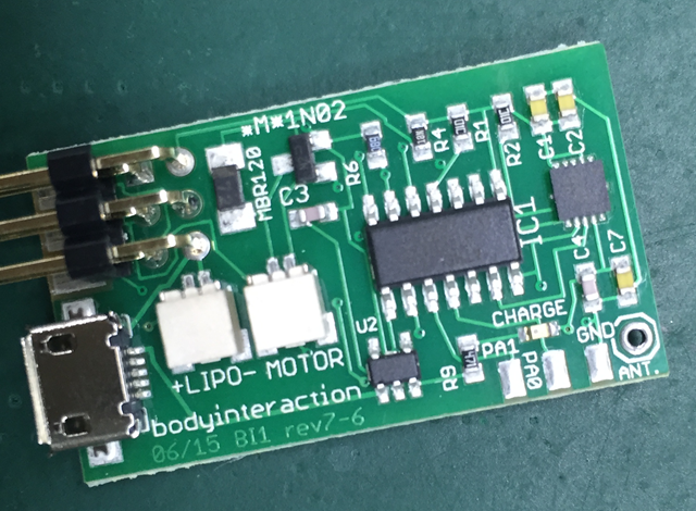
Now let’s build the first ESP8266 vibrator. I use the reliable design from this blog post and the new BI2 board. The new BI2 board can be controlled from any smart phone or computer.

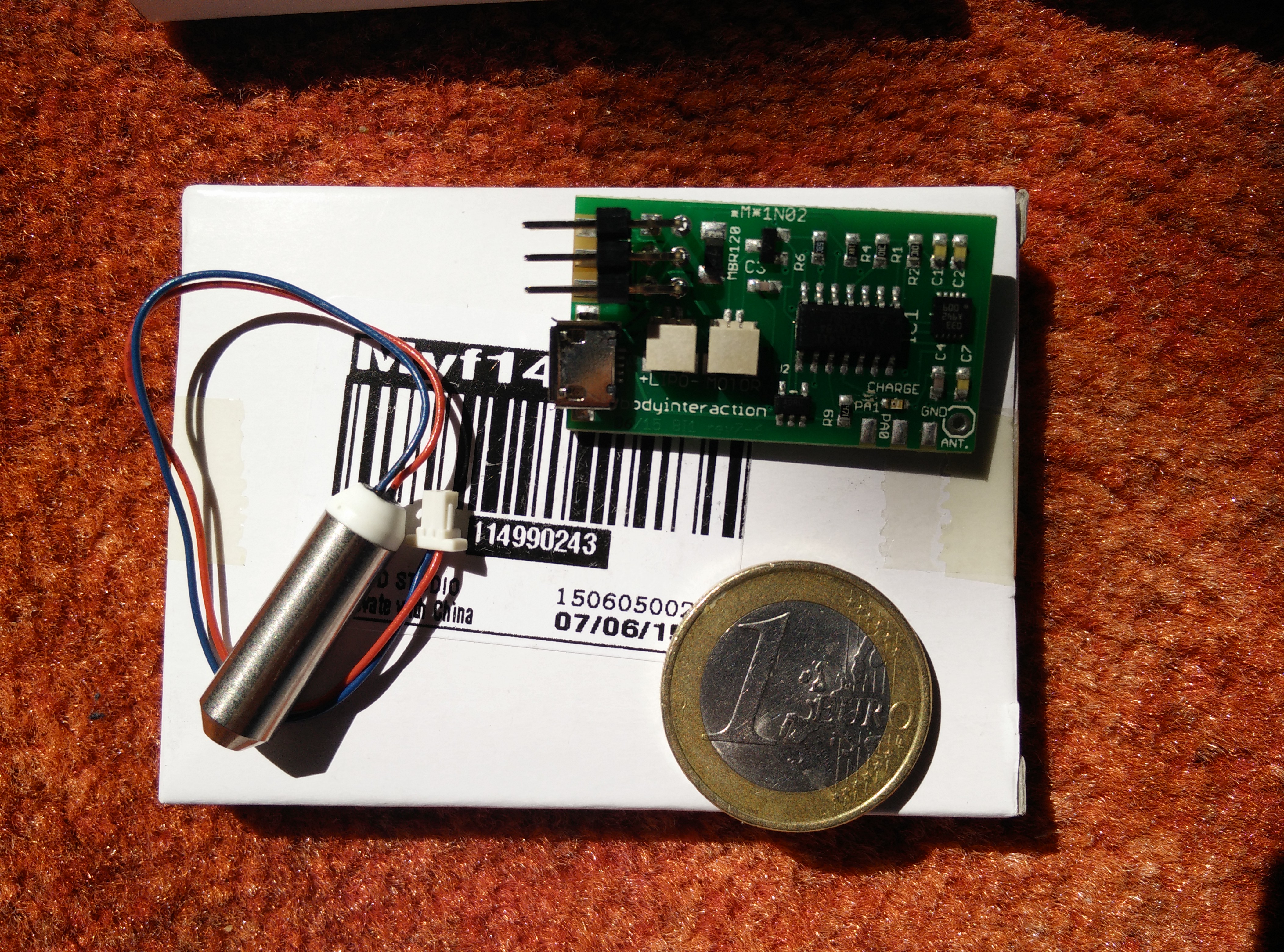
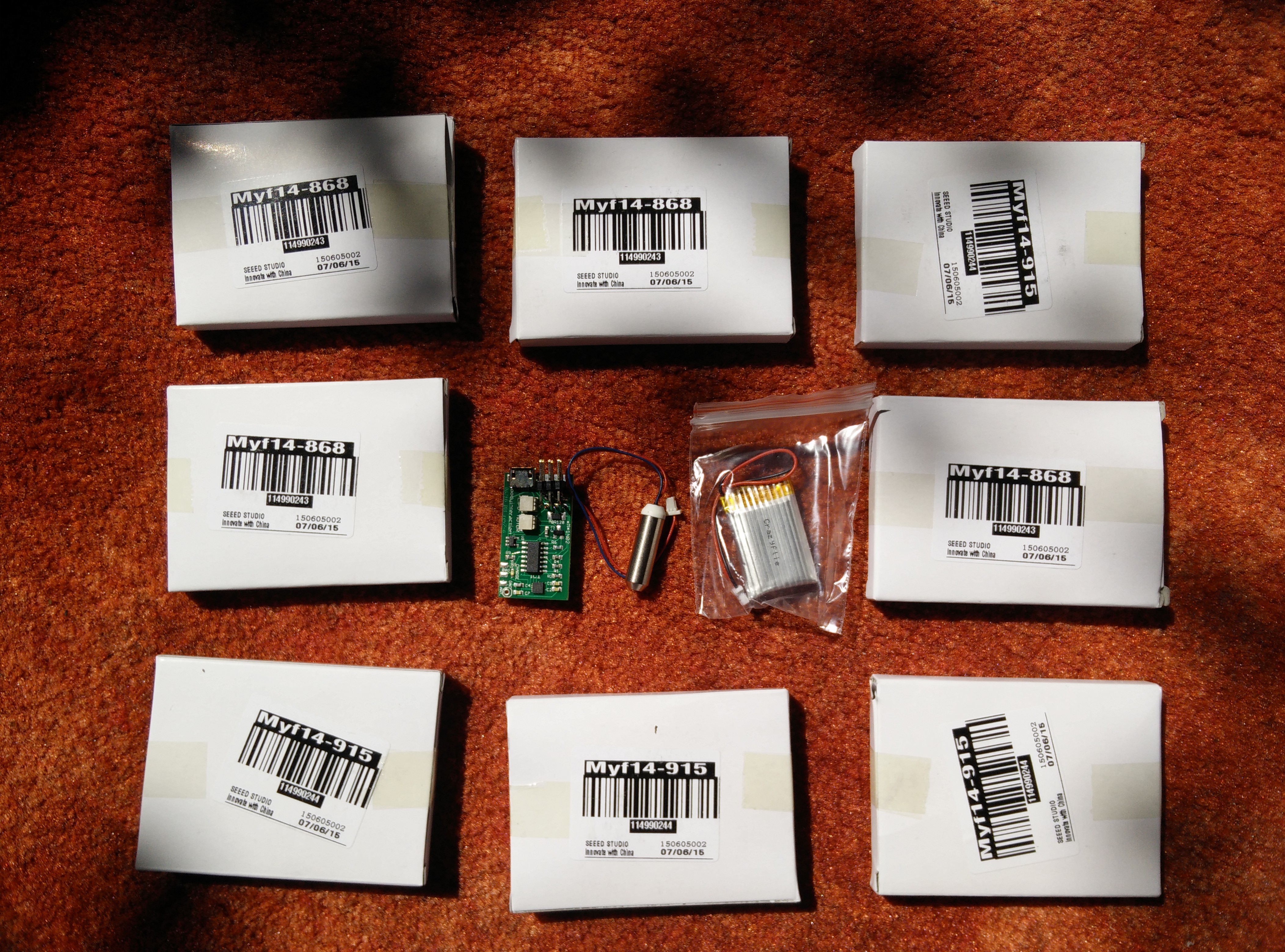
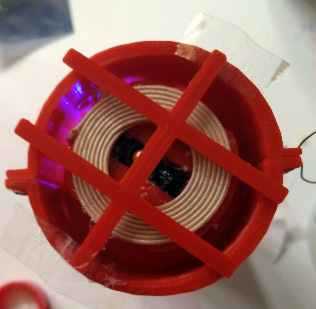
As the BI2 board is round there is no need to build a case for the PCB and the LiPo. The easist way is to glue the battery directly on the ESP8266. Connect the battery and one or more vibration motors with the BI2 board.


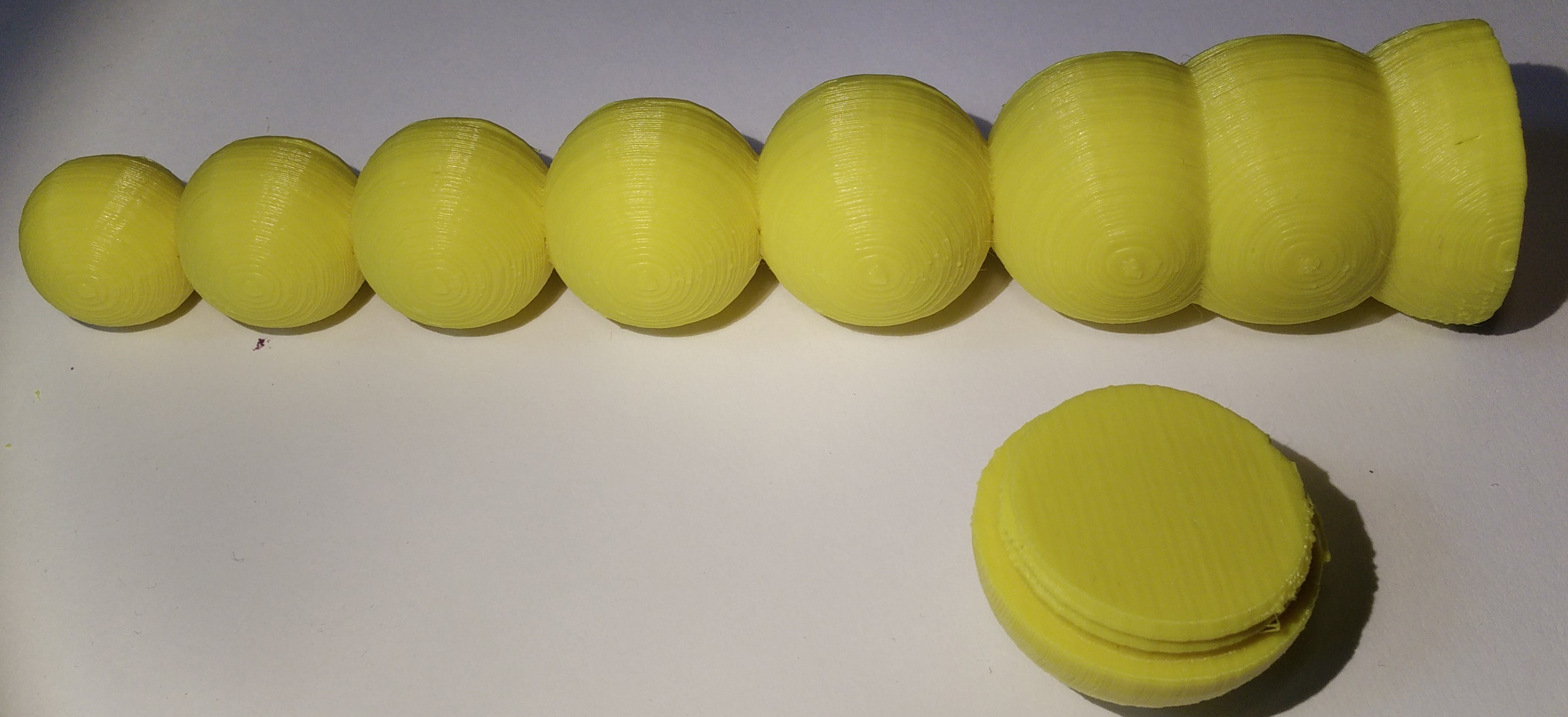
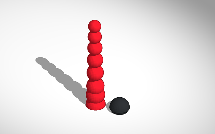
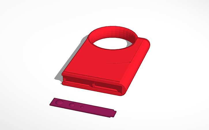
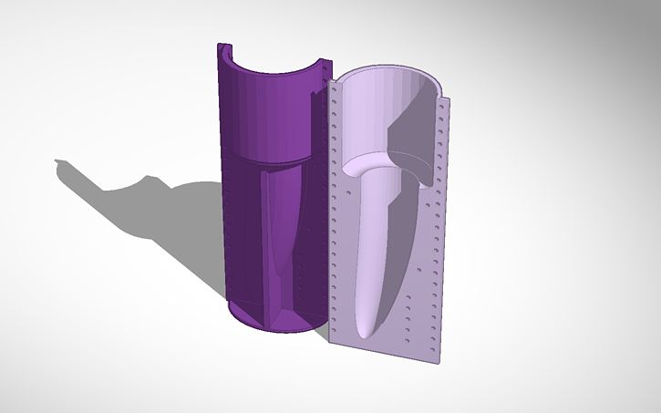
The form consists of two parts which are fastened together with tinker wire. Before you have to insert the board with the vibration motor(s) and the battery. Therefore I used a handle. The handle could be put on top of the form. Then fix a USB connector to the handle. Plug in the BI2 board. Fasten the second half of the form.

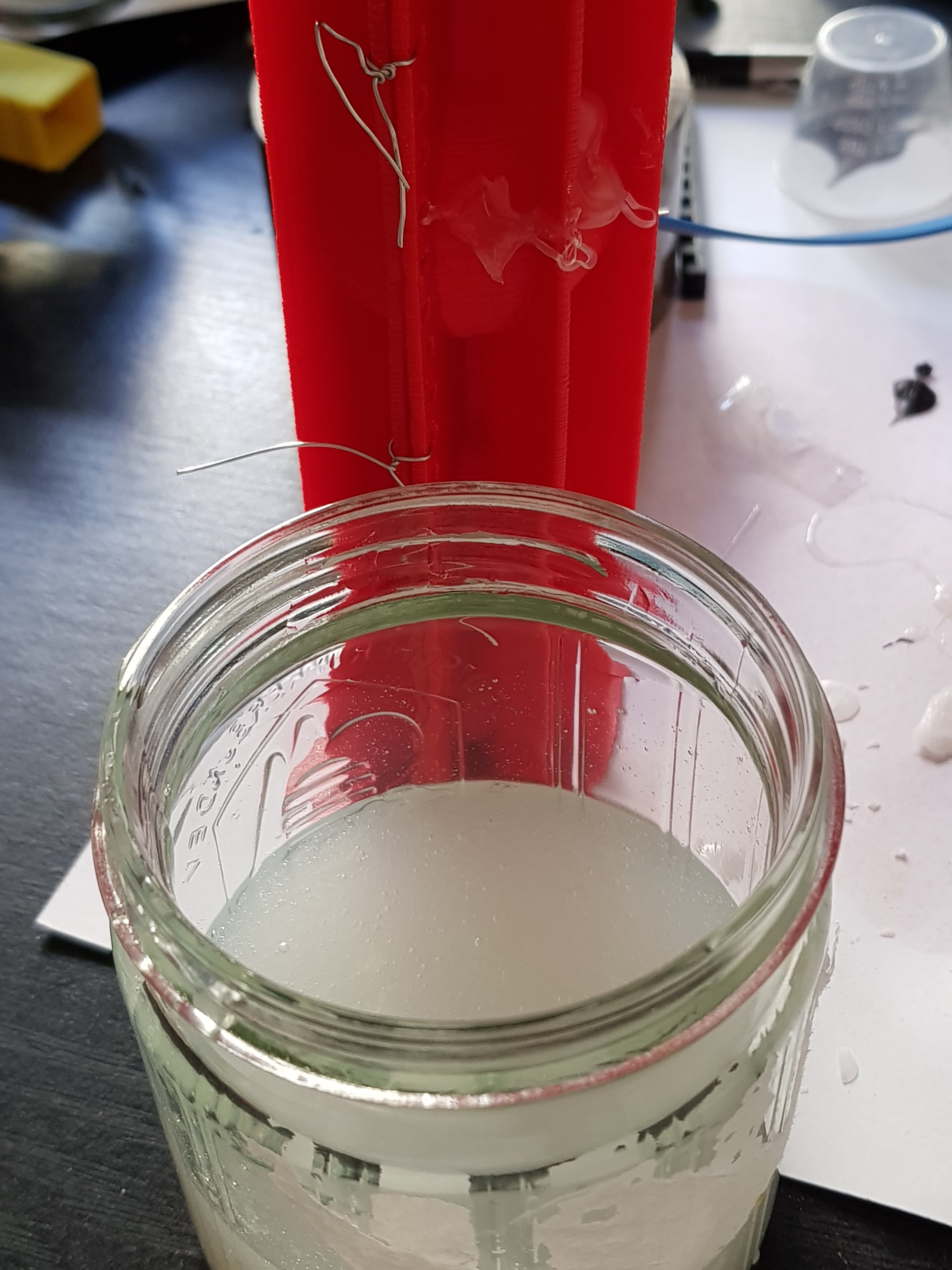
Very important: The USB micro connector on the board must be protected from the silicone. When silicone flow between USB plug and connector it will be impossible to pull out the plug. I use wax to seal the USB micro connector. Read more here.


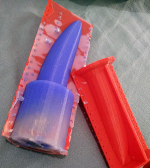
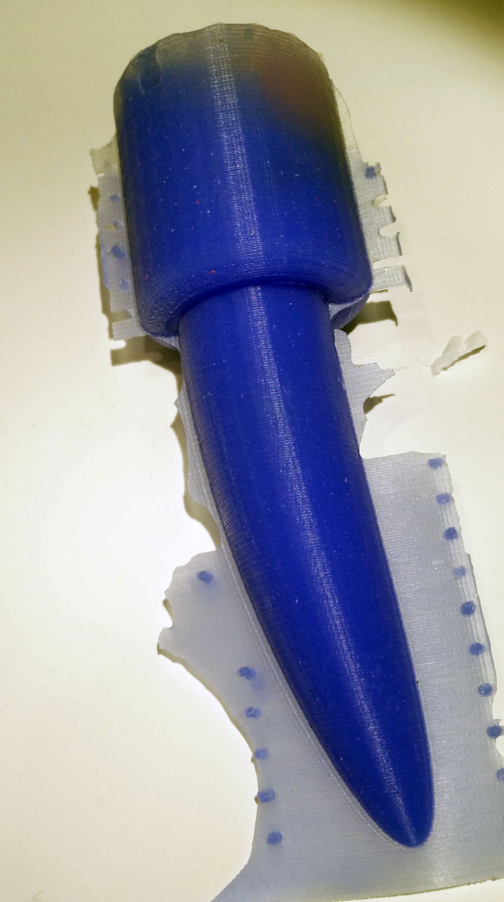
Now pour in the silicone, wait for some hours. And open softely the form.


Remove the overhanging silicone.

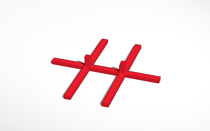
Here ist the Link to Tinkercad where you can edit the form and download STL files for your 3D printer: Download from Tinkercad: formhandle. Download ready to print zipped STL files.

Now build YOUR personal sex toy. Here you find the code for the ESP8266 as well as an IOT server application for quantifying your sex and remote control.

BI2: ESP8266 Vibrator Development Board – becoming colourful

The second version of the development board – I will call it BI2 from now on –  has some improvements:

  • I used more components of the original design (Adafruit Feather Huzzah) instead of comparable (and cheaper) Seeedstudio Open Part Library components. The reason for this is easy. The Adafruit design is reliable and approved. No need for designing your own circuits, no risk to fail. (But also no fun in inventing new circuits.)
  • I added LED light – the WS2812B – which is a  colourful LED (16 Mill. colours). They are commonly known as Adafruit Neopixel – a strip or a ring of individual programmable LEDs.
  • The diameter is smaller the first version.
  • It can drive three motors. (When you use the LED then only two motors can be driven.)

Here are some impressions of the board:


As you can see I had to wire the LED by hand. The reason for this is that I used GPIO16 which does not work at all. So I wired the LED to GPIO0 which can be used for testing only. The only free GPIOs are 12, 13 and 14.


Basic Node for the Internet of Sex Toys – part 2: 3d printed form, assembly, molding

In this series of posts we describe how-to make a vibrating sex toy which is part of the Internet of Things.

part 1: Basic Node for the Internet of Sex Toys

part 2: Molding the Basic Node

part 3: Software for the Basic Node

In part 2 we describe how-to make a mold form for the basic node. We need three forms:

  • the mold form which consists of two parts
  • the inlay which protects the electronics of the basic node
  • a “hanging” for the inlay


We used Tinkercad to construct the parts. The molding form is based on Tinkercad’s banana form. You can edit and share them from your browser:

Inlay: https://tinkercad.com/things/h5fFOBqlmjw

Hanging: https://tinkercad.com/things/jUxc2oAamww

Form: https://tinkercad.com/things/6HS3XScOsCM

Instructions

Print out all forms. The STL files are available at Thingiverse. You might want to use XTC or similar for smoothing the inner part of the mold form.

Assembling the Inlay

We use the inlay to protect the electronics.

Simply put the electronics inside so that the upper body of the switch is on the same level as the upper inlay. We use hot glue to fix the basic node.

Then fix the receiver coil of the wireless charging module on top of the inlay. The next step is to fix the hanging at the inlay.

Now fix the LiPo battery on the bottom side of the inlay using hot glue or similar. Fix the wires. Finally you might fix the wires of the vibration motor next to the middle of the LiPo battery.

Use tinkering wire to fix both parts of the molding form.

Put the inlay in the form. Fix the hanging with a tape or similar. The motors shouldn’t touch the inner part of the form.

Now prepare the silicone. We use Shore A 45 silicone (approx. 250 ml) from Silikonfabrik.de. It is hard but still a bit flexible. You may add color, too. You have about 10 minutes to stir the silicone and poor it in the form.

After some hours you can remove the form. As you can see there is overhang which make removing the form very hard. The form could break when removing. Better preparation of the form (eg rasping) could improve the results.

If the blue LED of the Wemos board is still active you were successful.

Now you need a charging station. The construction is shown here. It is also possible to connect the sender (or transmitter) module with a 5V power source (eg. from the USB port). Just put the bottom of the molded basic node on the sender coil.


In the next part we introduce an updated version of the software including over the air update and WiFi management.

Assembling the new violet vibrator form

IMG_20150901_211915[2]
We ordered the organic vibrator form from Sculpteo. They offer material which can be used for food – so it’s very safe.


IMG_20150901_212010[2]All you need for assembly is the body interaction motion controlled vibrator development board and two M3 screws (about 6mm long).


Assembled board

boards arrived one box


The video explains how-to assemble the Arduino compatible body interaction vibrator board and the form. Watch in Youtube

Unboxing and assembling of vibrator development board

The body interaction development board includes everything to start: the board, the LiPo battery and a vibration motor. Put it together in a few minutes. All you need now is a 3d printed case.

We give away a limited number of body interaction development boards for free. Please send a short description of your project with your email, mail address (and website) to info@bodyinteraction.com. Only available outside the US due to patent trolls.  Please send us a photo or video when the project is finished. Your data are not given to anyone else and will be deleted on request.

Video in Youtube

In the next post we show you how to assemble a 3d printed case and the body interaction development board.

vibrator development boards arrived

boards arrived one boxWe proudly annouce the arrival of the body interaction vibrator development board. Each board is packed in a small box. In this box is the board, a LiPo battery and the vibration motor. Connect motor and LiPo to the board and it works: The vibration motor changes speed according to your motions.

Thanks to Seeedstudio for this amazing work!


BoardsArrived1

box9x9assemble

New vibrator design for the vibrator development board & 3d cases

Chain of Ball 2

Chain of Ball Vibrator design with cap

The new design catches the “chain of balls” design theme used in some sex toys. It was constructed in Tinkercad and it is really simple to do it on your own. This how-to video explains the construction in detail.


many balls body interaction vibrator development board

The design is composed from several spheres

Try it on your own in Tinkercad. Just grab a sphere, make a copy, resize the copy, make a copy again and repeat this until you have a chain of spheres. Now select all sphere and use the “align” tool. That’s it.

The tricky part is the screw cap. This is needed to enclose the body interaction vibrator development board.


Chain of Ball vibrator being printed

Chain of Ball vibrator being printed in ABS, XYZ printer 1.0, on the bottom is the support material

Improved vibrator ring

Ring2_6There is new version of the vibrator ring. The height is smaller than in the original version. As there must be enough space for the vibrator development board, the LiPo battery and the vibration motor the case is larger in height. Board and LiPo are now beside one another. The new case is printed with the daVinci 1.0  3d printer with yellow ABS.

Vibrator ring 2 - 3dModify and create your own with Tinkercad. Or download from Thingiverse.

Dimensions: 78x48x10mm

Improved version! Open with Tinkercad.  Download from Thingiverse.