Tag: development board

The new BI2 black vibrator development board

The new black BI2 board is ready. I have a few assembled boards ready for shipping. Have a look at www.tindie.com

3 JST 1mm plugs (battery, motor 2, motor 3), LED, reset button, M+/M- is for motor 1

JST 1mm plug for motor 1, alternative RESET button

Features

  • ESP8266 Microcontroller with WLAN
  • MPU9250 (accelerometer, gyroscope)
  • LiPo battery charging
  • 3 motors can be connected (simple motor driver circuits)
  • 1 WS2812B LED – a  colourful LED (16 Mill. colours). They are commonly known as Adafruit Neopixel – a strip or a ring of individual programmable LEDs (when use the WS2812B only two motors can be connected)
  • design based on the great Adafruit Feather Huzaah ESP8266
  • vibration motors and LiPo battery can be easily connected with JST 1mm connectors
  • two reset buttons (the button next to the USB connector can be overmolded)
  • USB connector for battery charging and code uploading
  • programmable with the Arduino IDE or NodeMCU
  • white LED for indicating charging
  • standard LED (yellow) on GPIO00
  • round 40mm diameter


There are 3 free GPIO ports. Standard layout are for driving 2 motors (GPIO 12 = M2, GPIO 13 = M3) and 1 LED (GPIO14). Alternatively you can use 3 motors (GPIO12,13,14) but no LED.

Standard: SJ2 not connected, SJ3 connected

Alternative: SJ2 connected, SJ3 not connected


Here is the schematic which is adapted from Adafruit.

References:

  • Quick start up guide with Blynk app is here
  •  Assembling a silicone molded vibrator with 3D printed form – tutorial here
  • Complete guide including wireless charging, control with Node-RED and data transmission via MQTT is here

Blynk: Controlling BI2 from the smartphone

Readers ask me for an easy way to control the body interaction vibrator development board. Without or with limited  programming knowledge, without complicated Internet of thing technology, like the visual programming tool NODERED or the MQTT protocol and server.

That’s what Blynk is for. Started in 2016 as a kickstarter  campaign, they have built a tool which hides a lot of the complexity of the Internet of Things. Blynk consists of the following parts:

Blynk app. With this app you can build a User Interface in just a few minutes. You have all the usual elements like switches, slider,  graphs and much more for controlling IOT devices.

Blynk Server / Cloud is responsible for the communications between the smart phone and IOT devices. There is nothing to do, everything works in the background

IOT devices library: So far everything is very simple. But at the end you have to program your IOT device – the body interaction 2 board for example. They support a great number of boards. For this they created the blynk  library – with the library you need only some lines of code which must be uploaded to the board. Even when you change the user interface the code can stay the same. At least for simple changes. They offer a code generator where you code for your board and use case is generated automatically.

You find a lot of information in the Internet about the pros and cons. In short: It is easy compared to other tools, but if you want to implement your own algorithms programming knowledge is needed. Blynk limits the number of free User Interface elements. If you need more you have to pay  a small fee.


Here is short tutorial to run you BI2 with Blynk. (takes 30 minutes)

Download the Blynk app (Android or iPhone).

Within the Blynk app: Register for Blynk and get AUTHenitfication code.

Upload Arduino

You can download Arduino from the Arduino Website or from the Microsoft Store (Windows only)


Add or update the following libraries with the library manager: FastLED and Blynk.

Select Include libraries -> library manager

Search for FastLED and install this library (press install button).

Now search for “Blynk” and install the Blynk software. However Blynk suggests to install the Blynk app manually.


Add board definition for the ESP8266

Select Tools -> Board -> Board management

Search for ESP and install “esp8266”

Select Board -> Adafruit Feather

Build a connection between BI2 and your computer.

First download the USB driver from here and install the driver. Connect the BI2 with your computer. After some while windows will notice a new device. Windows will communicate with the board over a COM port (e.g. COM3). If you have any problemes check your USB wire. It must support all lines, not only + and – for charging.

Now go back to Arduino and select Tools -> Port. Select the new COM portcom port arduino

Compile and upload the code to BI2 board

Now copy and paste the following code in a Arduino sketch (use File -> new). Then press the Upload button.

/*************************************************************
Controling the body interaction 2 board with the Blynk app
*/

#define BLYNK_PRINT Serial
#include <ESP8266WiFi.h>
#include <BlynkSimpleEsp8266.h>

// Auth Token infor the Blynk App.
char auth[] = "XXXXXXXXXXXXXXXXXXXXXXXXXXX";

// Your WiFi credentials.
char ssid[] = "XXXXXXXX";
char pass[] = "XXXXXXXX";

// Library for controlling the WS2821B (Neopixel) LED or LED strip
#include "FastLED.h"
#define NUM_LEDS 1 // number of LEDs
#define DATA_PIN 14 // pin for LED
CRGB leds[NUM_LEDS]; // define the array of leds

// This function set the LED color according to the selected RGB values in the app.
// RGB values are controlled in the app with zeRGBa widget
// values are stored in the virtual pin V0
// V0 consists of 3 values for Red, Green, Blue
BLYNK_WRITE(V0) // set LED RGB color values
{
  int i = param[0].asInt();
  int j = param[1].asInt();
  int k = param[2].asInt();
  leds[0].setRGB(j,i,k);
  FastLED.show();
}

void setup()
{
  // init LEDs
  FastLED.addLeds<WS2812B, DATA_PIN, RGB>(leds, NUM_LEDS);

  // connect to Blynk
  Blynk.begin(auth, ssid, pass);
}

void loop()
{
  Blynk.run();
}

You have to change AUTH. Use the AUTH code / token that was sent to you during Blynk registration. Then you have to change the WLAN credentials. Use the name of your network (SSID) and its password. (Depending on the maximum voltage of the vibration motor you have to adjust i, j and k e.g. for a 1.5V motor divide the variables by 3.

Configure the Blynk app

Create a new project and choose this device: ESP8266. Now add user interface elements – they are called widgets -to control the BI2. You can move and resize, add and delete each widget. Press on the widget to enter parameters like GPIO port etc. The app could look like that but you may position the widgets as you like. [The pitch, roll, yaw text fields can be omitted. They are introduced later.]

Add the following Widgets

Press the “+” button and add this widget:

zeRGBA: With this tool you can control the WS2821B LED

Choose select pin V0 = Virtual Pin 0.

Choose Merge.

Send on release: off

Add Sliders

Press the “+” button and add two sliders, one for each motor.

1st silder: Select Digital Pin 12 (PWM)

2nd slider:  Select Digital Pin 13 (PWM)

Add Button

Press the “+” button and add the button widget. Select pin digital – gp0. Set mode to “switch”.

Start the app

Therefore press the Run (or play) button (top left).


Done!

Questions? Reply to this post, via wordpress or to jacardano@gmail.co


BI2: ESP8266 Vibrator Development Board – becoming colourful

The second version of the development board – I will call it BI2 from now on –  has some improvements:

  • I used more components of the original design (Adafruit Feather Huzzah) instead of comparable (and cheaper) Seeedstudio Open Part Library components. The reason for this is easy. The Adafruit design is reliable and approved. No need for designing your own circuits, no risk to fail. (But also no fun in inventing new circuits.)
  • I added LED light – the WS2812B – which is a  colourful LED (16 Mill. colours). They are commonly known as Adafruit Neopixel – a strip or a ring of individual programmable LEDs.
  • The diameter is smaller the first version.
  • It can drive three motors. (When you use the LED then only two motors can be driven.)

Here are some impressions of the board:


As you can see I had to wire the LED by hand. The reason for this is that I used GPIO16 which does not work at all. So I wired the LED to GPIO0 which can be used for testing only. The only free GPIOs are 12, 13 and 14.


Making of an ESP8266 Vibrator Development Board – traps and pitfalls

About a year ago I made a ESP8266 based design for a vibrator development board including IMU, motor driver and battery charging. The design was based on the Adafruit ESP Huzaah, but I used components of Seeedstudio Open Parts Library. This is a library of parts (IC, connector, resistors) which are stocked at Seeedstudio especially for their PCBA (printed circuit board assembly) service. PCBA is really great. Instead of tinkering and soldering on your own you can send the design to Seeedstudio, they make the printed circuit board and assemble all parts. Unfortunately the main part – the ESP8266 microcontroller – was missing in the Open Part Library . So I turned to use the affordable ready-made WeMos ESP8266 boards (see here).

In June 2017 I took a closer look at the PCBA service. At that time the OPL offered two variants of the ESP8266. But even better: You could order almost any part. The difference between using OPL parts and other parts was the time for the assembly as it takes more time to order parts which are not on stock.

So I ordered two boards. The boards are round with a diameter of 5 cm (that’s the size of a wireless charging coil). As I had a coupon the two boards were only about 50US$. Including delivery! And even better: Seeedstudio delivers from a logistic company in Germany. So I had not to pay any taxes. Great. But… unfortunately … I made beginner’s mistakes…during design.

  1. Problem: As the board should be programmable by USB connection you need a USB to serial bridge eg. one of the FTDI ICs. This bridge has two important connections TX (transfer) and RX (receive). And the ESP8266 has the same TX and RX. But don’t connect them. Instead you have to connect RX to TX and vice versa. (Well I should have know, when I soldered null modems maybe 20 years ago or more…)

    Taken from Sparkfun

  2. Problem: When using the serial monitor of the Arduino IDE you need another connection: RTS (ready to send). Unfortunately the used serial bridge – the FTDI FX230XS IC – had no RTS. (There is a circuit which works without RTS, but I didn’t know.)
  3. Problem: I used GPIO0 for driving the motor, that’s why auto reset doesn’t work. So I had to short-cut GPIO0 and GROUND for uploading a script.

So I tried to fix the problem. At first I had to cut the wrong connections. On the bottom side of the board the RX and TX wires are quit good accessible. So I could cut them using a dremel.

In the next step I had to connect the RX and TX headers of the FTDI chip with the ESP 8266…

The green clamps were used to shortcut another wrong connection.

Finally upload with the Arduino IDE was possible, but no debugging using the serial monitor. Battery charging seemed to work, too, although this needs more time for testing. WiFi worked. Essentially I could upload a script which made one LED blinking. And I could start the WiFi manager.

Debugging such a complex thing like a ESP8266 without serial connection is almost impossible. But then I found RealTerm. This is the only terminal program for Windows where you have all options to use or not use serial sync mechanisms like DTR, RTS etc. It is made to make a serial connection work even if you have only TX, RX and GROUND.

Here you can decide to ignore RTS and/or DTR by pressing “Clear”. (Read more about this here.)

.

And finally it worked. The ESP8266 sends debug text to the serial monitor. The transmission maybe scrambled, but it is still readable. Realterm – a really great tool for debugging serial connections.

Readings of the MPU9250 (accelerometer, gyro)

Probably it is more reasonable to use a bread board for the development of a design. But customizing an open source design on the PC and then get it assembled for a reasonable price – for me it’s like a dream come true. But as you see – all your efforts can be worthless.

But I will do it again…


Basic Node for the Internet of Sex Toys – part 2: 3d printed form, assembly, molding

In this series of posts we describe how-to make a vibrating sex toy which is part of the Internet of Things.

part 1: Basic Node for the Internet of Sex Toys

part 2: Molding the Basic Node

part 3: Software for the Basic Node

In part 2 we describe how-to make a mold form for the basic node. We need three forms:

  • the mold form which consists of two parts
  • the inlay which protects the electronics of the basic node
  • a “hanging” for the inlay


We used Tinkercad to construct the parts. The molding form is based on Tinkercad’s banana form. You can edit and share them from your browser:

Inlay: https://tinkercad.com/things/h5fFOBqlmjw

Hanging: https://tinkercad.com/things/jUxc2oAamww

Form: https://tinkercad.com/things/6HS3XScOsCM

Instructions

Print out all forms. The STL files are available at Thingiverse. You might want to use XTC or similar for smoothing the inner part of the mold form.

Assembling the Inlay

We use the inlay to protect the electronics.

Simply put the electronics inside so that the upper body of the switch is on the same level as the upper inlay. We use hot glue to fix the basic node.

Then fix the receiver coil of the wireless charging module on top of the inlay. The next step is to fix the hanging at the inlay.

Now fix the LiPo battery on the bottom side of the inlay using hot glue or similar. Fix the wires. Finally you might fix the wires of the vibration motor next to the middle of the LiPo battery.

Use tinkering wire to fix both parts of the molding form.

Put the inlay in the form. Fix the hanging with a tape or similar. The motors shouldn’t touch the inner part of the form.

Now prepare the silicone. We use Shore A 45 silicone (approx. 250 ml) from Silikonfabrik.de. It is hard but still a bit flexible. You may add color, too. You have about 10 minutes to stir the silicone and poor it in the form.

After some hours you can remove the form. As you can see there is overhang which make removing the form very hard. The form could break when removing. Better preparation of the form (eg rasping) could improve the results.

If the blue LED of the Wemos board is still active you were successful.

Now you need a charging station. The construction is shown here. It is also possible to connect the sender (or transmitter) module with a 5V power source (eg. from the USB port). Just put the bottom of the molded basic node on the sender coil.


In the next part we introduce an updated version of the software including over the air update and WiFi management.

Basic Node for the Internet of Sex Toys (part 1)

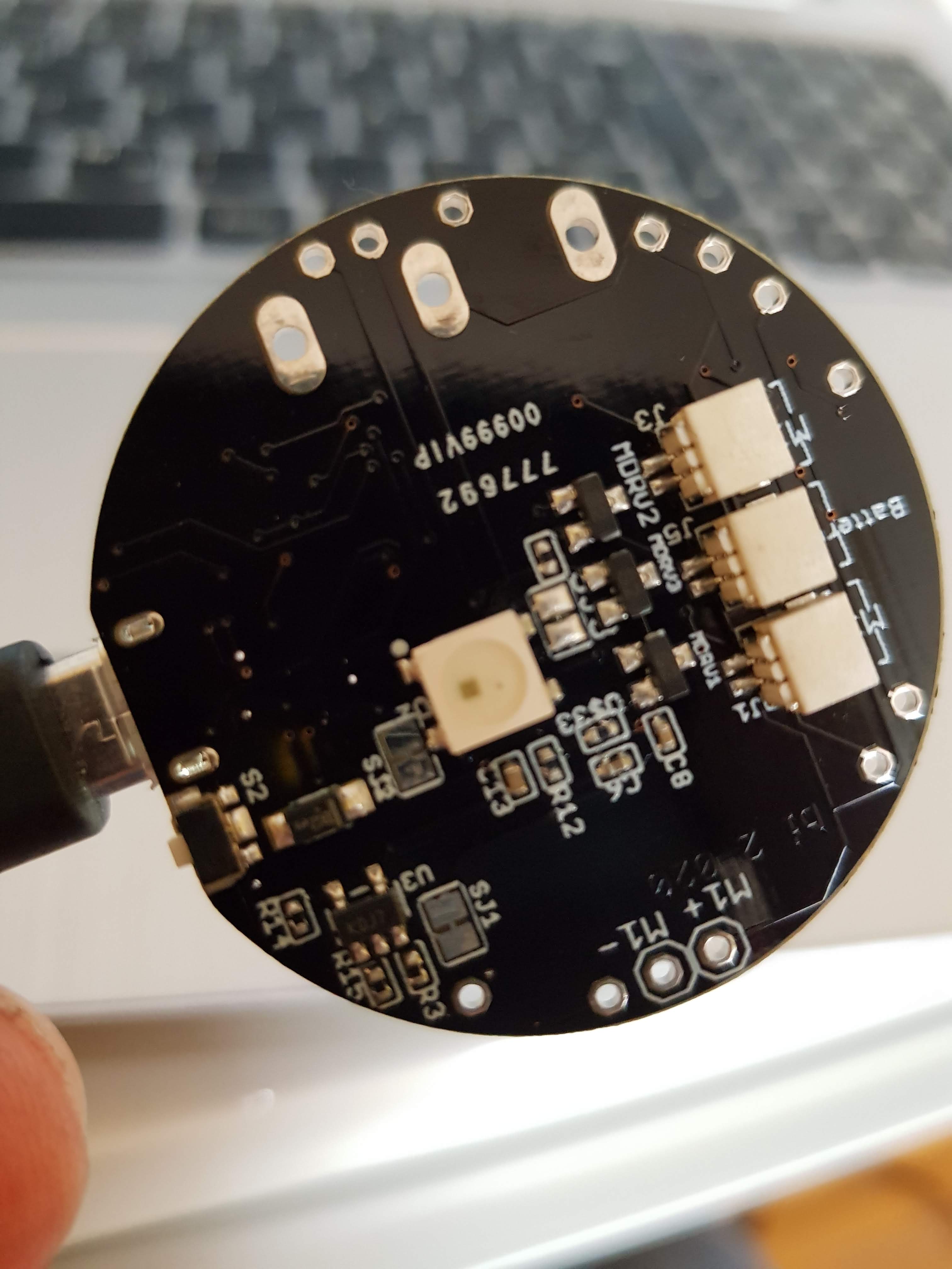
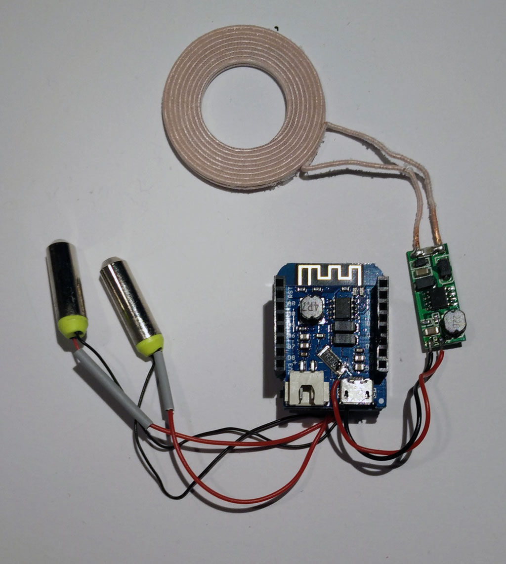
Wemos mini modules: ESP8266, motor driver and battery charging (in the middle); Wireless charging module (right side); wireless charging coil (top side); encapsulated vibration motors (left side)

In previous posts we showed how to build a vibrating sex toy in principle as part of the Internet of Things (IOT). In addition we have selected a hardware platform – the popular ESP8266 – for controlling a vibrator motor, gathering motion data and connecting to the internet. Now we want to build the toy itself.

part 1: Basic Node for the Internet of Sex Toys

part 2: Molding the Basic Node

part 3: Software for the Basic Node

Brief Review of development boards

There are a lot of development boards which are equipped with the ESP8266. The popular NodeMCU was already introduced here. Here is a quick overview and comparison:

NodeMCU

  • plus: very popular, cheap, USB connector for programming
  • minus: quite large (for being part of a sex toy), no support for battery charging

Adafruit Feather Huzaah ESP

  • plus: USB connector for programming and battery charging, smart form factor (only 23 mm wide), very good support (libraries, tutorials)
  • minus: quite expensive

WeMos D1 mini (pro)

  • plus: very cheap, USB connector for programming, additional stackable modules (eg. battery charging, TFT screens, motor driver), good form factor
  • minus: no real support (but there is a forum, problems with modules reported

ESP8285 (variant of the ESP8266)

  • plus: really small (!!!) and smart form factor, USB programming and battery charging, optional sensors on board (but no motion sensors)
  • minus: quite expensive, only 1MB memory (nevertheless enough for a lot of application)

For our project we selected the WeMos mini cause we get almost everything we need:

  • USB connector for programming
  • module for battery charging
  • module for a motor driver
  • good form factor (eg. to be put in a vibrator handle or in the base of a dildo)
  • cheap, fast delivery

But there is no shield for motion detection (accelerometer,gyroscope). So we have to use an additional board eg equipped with the MPU9250.

But there is a problem with the WeMos motor shield: After a few seconds it stopped working. And in addition the MPU9250 stopped working, too. Hours and hours we tried different configurations, changed the libraries … The problem was the motor driver shield itself. Fortunately there is an easy work around. Read here.

Another issue is the battery shield. It has an extra USB connector for charging the battery. So you have two USB connectors (one for battery charging and one for uploading). Two USB connectors are not handy. Fortunately we can do without the USB connector for uploading as it is possible to update the software over the air (OTA) using WiFi.

Material

As the body interaction philosophy uses motion for controlling the device we have to add the MPU. Again we use the MPU9250 which has an accelerometer, gyroscope and magnetometer.

Another insight was that you need at least a switch for rebooting. As we want to mold everything the switch must meet the IP67 requirements, which means it is water- (and silicone) proof. If you don’t want to mold the electronics you can use the RESET button on the WeMos mini board.

A perfect basic node has a wireless charging option, too.

Material list for the basic node:

  • Wemos mini board
  • Wemos motor driver shield
  • Wemos battery shield
  • Wemos prototyping board
  • Wemos set of pins
  • LiPo battery (eg. 3,7V 650mAh, 2C, JST plug, available at ebay)
  • MPU 9250 board (for motion control)
  • 1 or 2 encapsulated vibration motors, 3V, available at Alibabaexpress
  • Optional: Switch IP 67 protected (eg. Cherry Switches DC1C-K8AA IP67) – for molding
  • Optional: Wireless charging receiver 5V eg from Seeed Studio

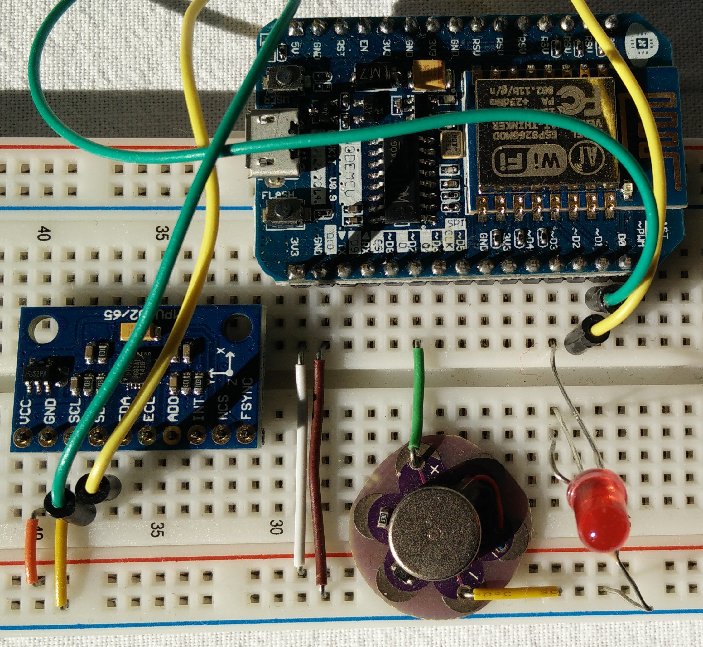
Material: battery shield, Wemos mini ESP8266, motor shield, MCU9250 (first row), LiPo battery, switch, vibration motor (second row)


Soldering the basic node

We use one connector (part of the Wemos set of pins) to connect the Wemos mini with the battery shield and the motor shield. This is done to save space. If your application has enough space you would use one connector for every shield.

Battery shield, Wemos mini ESP 8266, motor shield (from top to bottom)

Now have a look at the bottom side where the motor shield should be. We can connect up to 2 motors. Solder motor 1 to A1 and A2. Motor 2 has to be soldered to B1 and B2. In addition we need input power for the motor. We just use the 5V provided by the Wemos mini battery shield. Connect 5V to VM and GND (from the pins) and GND. But you could use other (more powerful) power sources, too.

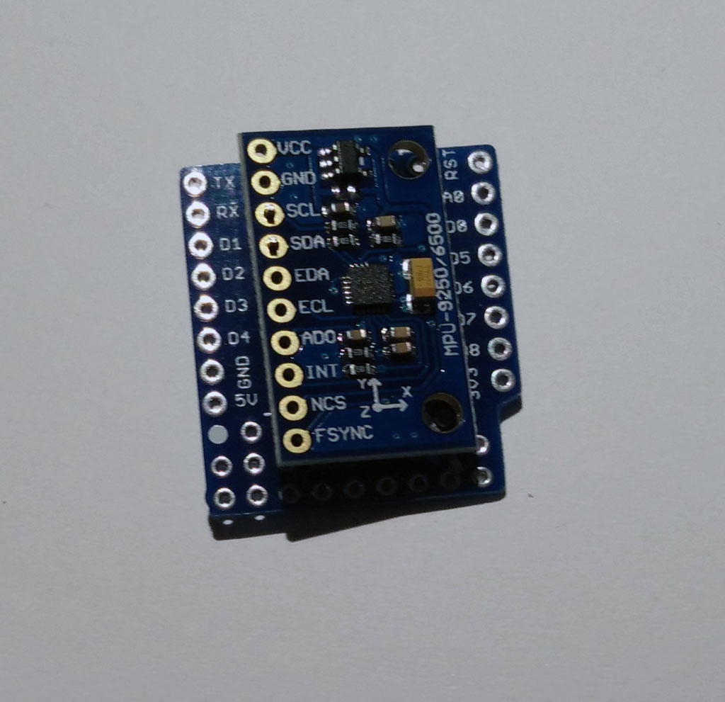
Wemos offers a prototyping board. We use it for mounting the switch and for the MPU9250. Connect the MPU9250 to the bottom side of the prototyping board. Therefore 4 pins have to be soldered

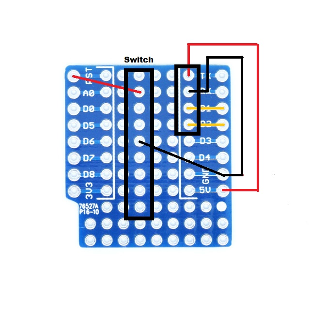
Solder pin (1 row, 4 pins)  on the top side next to TX, RX, D1, D2


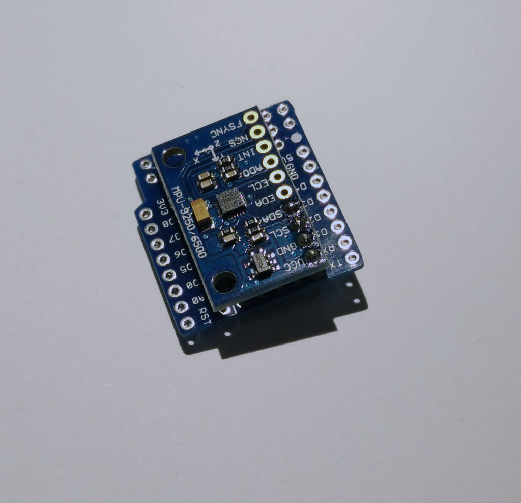
Now look at the bottom side of the prototyping board. Put the MPU 9250 so that VCC, GND, SDA, SCL are connected to the pins.

Next, solder the MPU 9250.

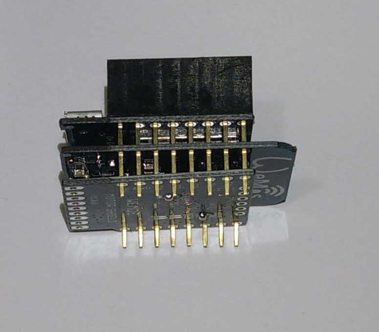
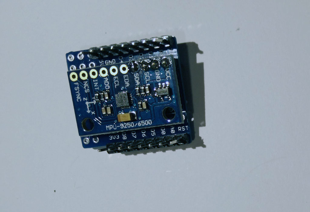
Then add more pins to the prototyping board at both sides. The picture shows the bottom side of the prototyping board.

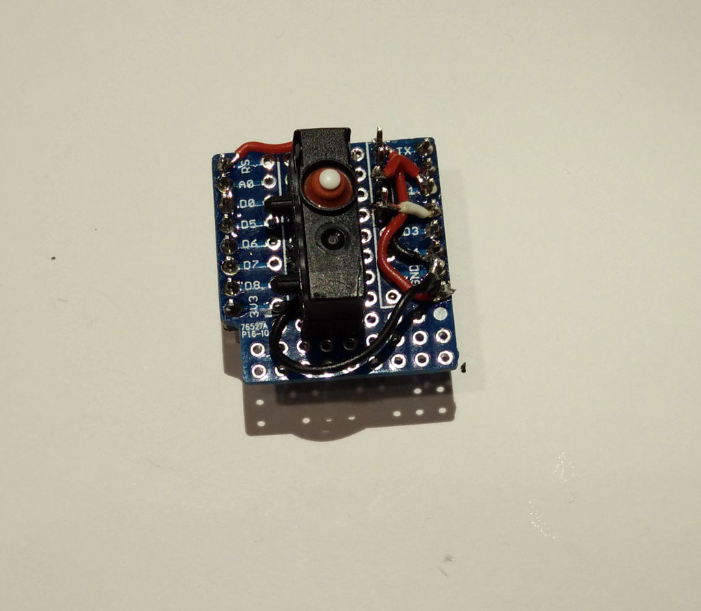
Now wire the prototyping board. The picture shows the top side.

Now you can add the switch. Place it in the middle of the board on the top side. Connect GND and RST to the switch. Now you have a switch for rebooting which can be molded.

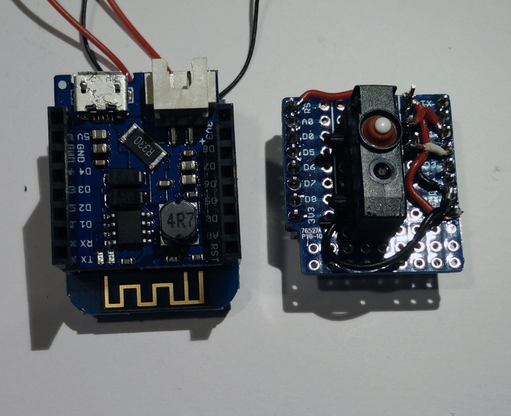
Now we have both parts ready and can stack them together.

Stack them together!

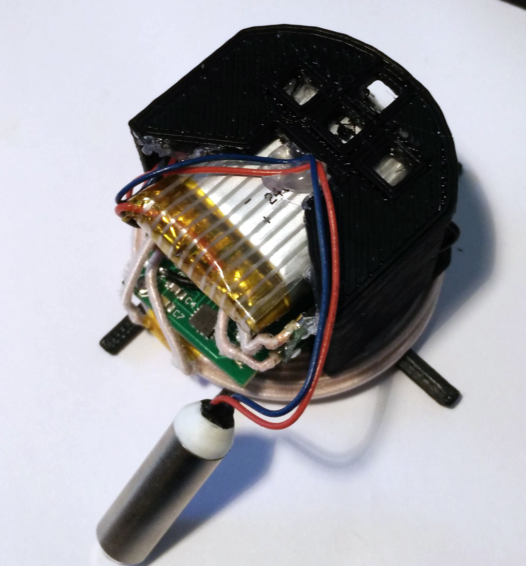
Now add the LiPo battery, which should have a JST header. Now your basic node is ready.

Wireless charging option

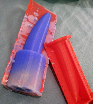
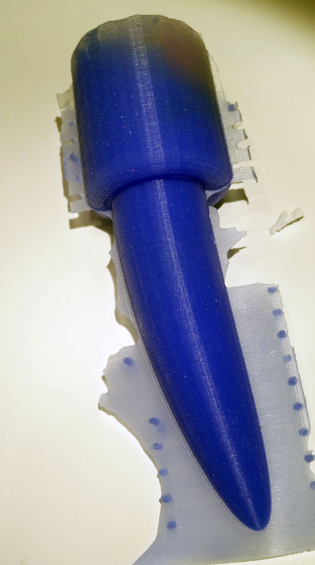
Especially for sex toys a wireless charging option is reasonable as this is a requirement for silicone molding of the toy.  And when the toy is molded it is safe and washable.

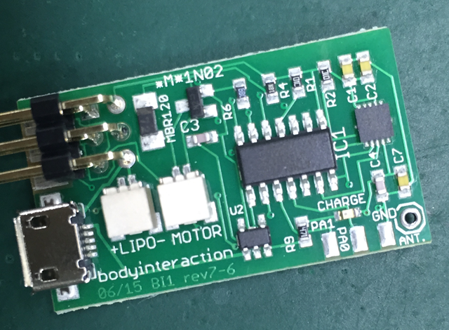
The wireless charging module consists of a sender (or transmitter module) and a receiver module. You have to solder the receiver module to the battery shield. Don’t mix the modules.

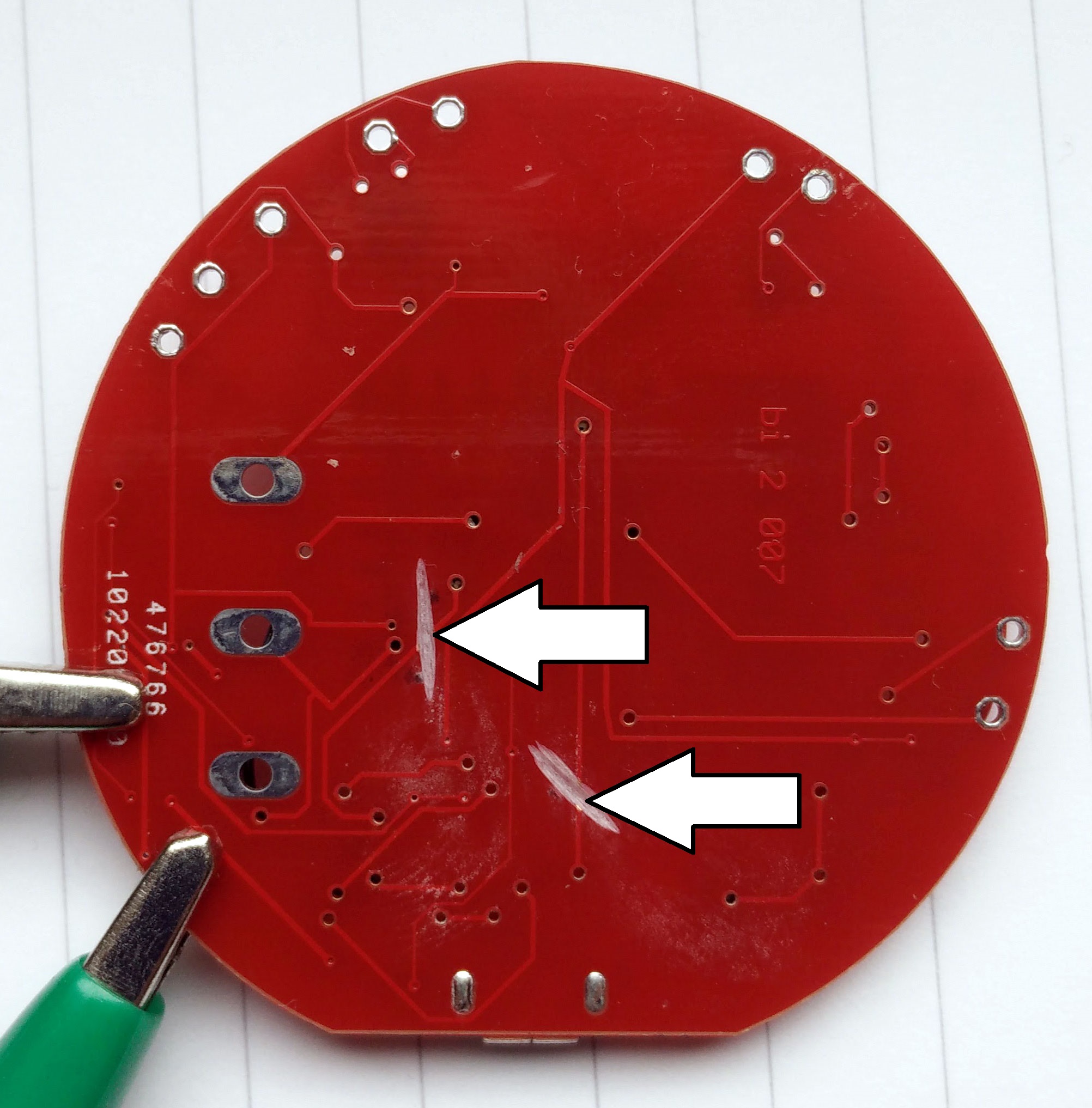
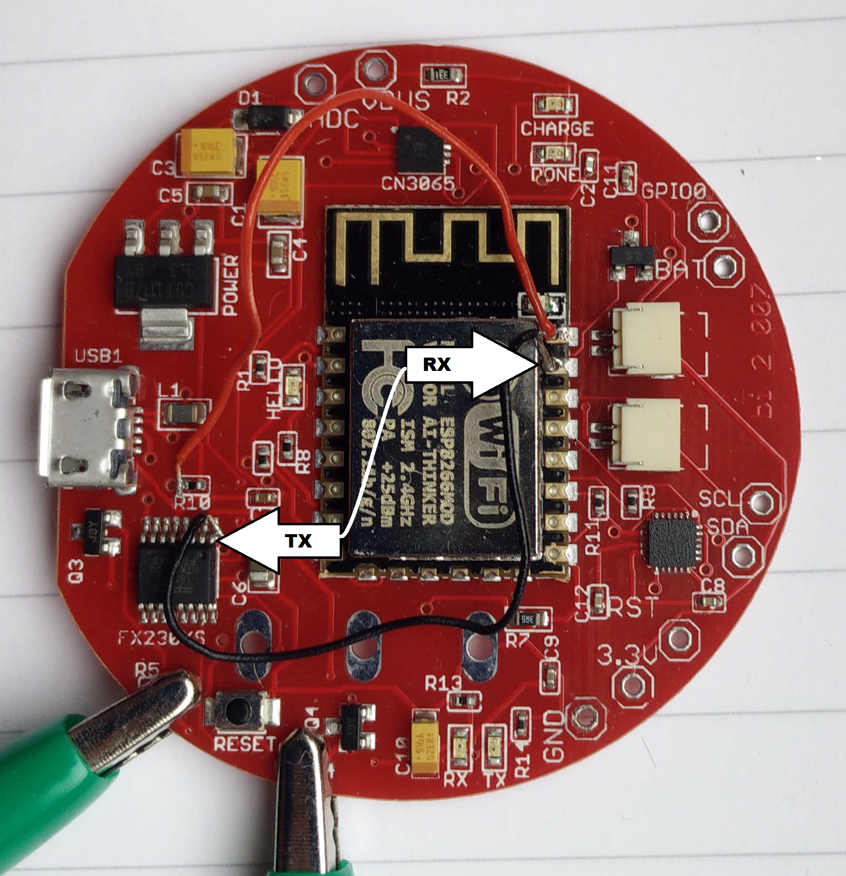
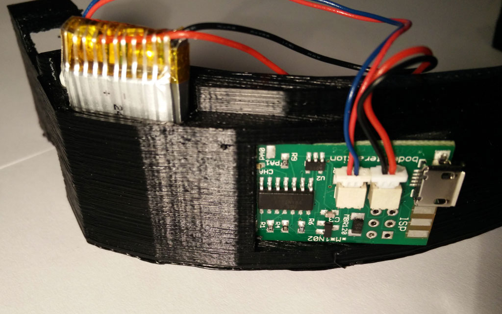
unfortunately there is only  a USB connector. If you don’t want to remove the USB connector you can solder the red (+) wire to the R330 resistor as shown on the pictures. The black (-) wire can be soldered to any pin labeled (GND).

Now put the receiver module on top of the battery module.

Now stack the protoytping board on top of the battery shield.  And connect the battery.
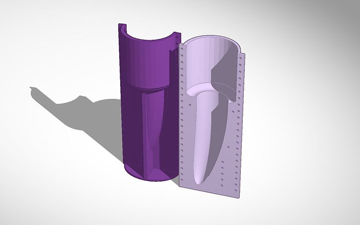
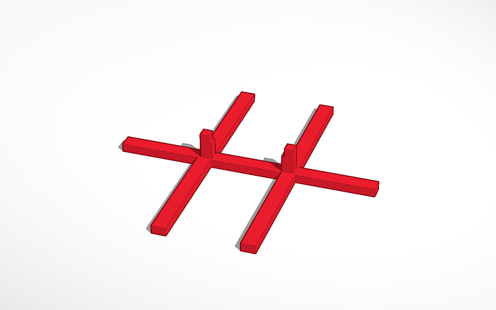
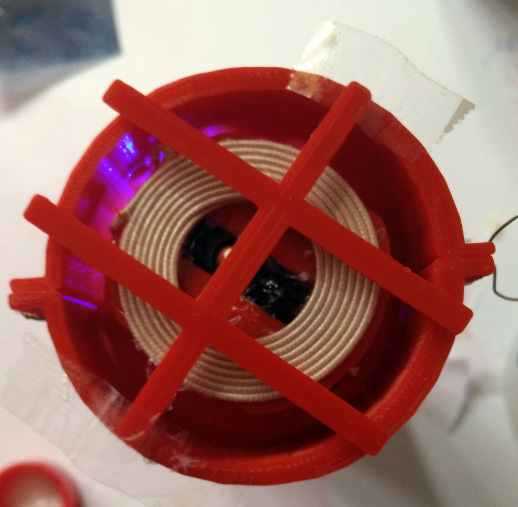
To charge the battery connect the sender (or transmitter) module to 5V. To power the sender module you may use a USB port power source which has about 500mAh or more. Place sender and receiver coil about each other.  For a more professional charging solution you need a charging station. The making of a charging station using 3d printing is described here.

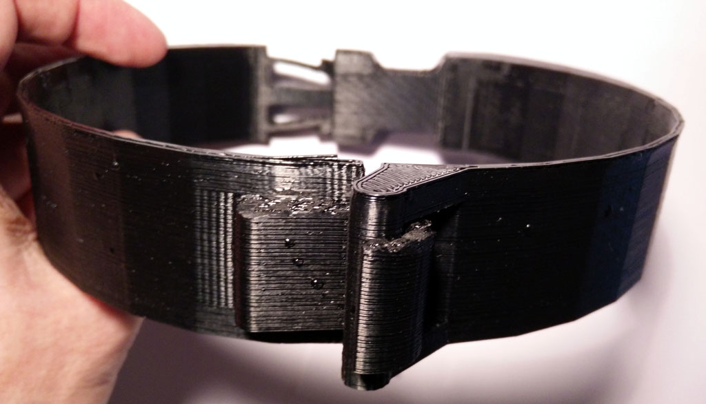
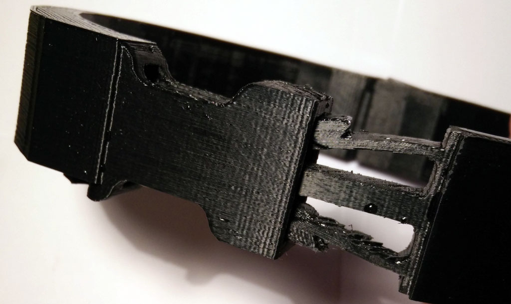
Learn how to construct the mold form in part 2:

part 2: Molding the basic node

part 3: Software for the basic node

Exploring the internet of (sex) things 1

The internet of things – or short IOT – is getting popular. IOT is a network of physical things like vehicles, buildings, but also everyday objects like lamps, refrigerators. IOT allows objects to be sensed and controlled remotely across the Internet. As a result the physical world will be integrated into the internet and computer systems.

Popular examples are home axiomatization or collection of environmental data.  Even sex toy industry use the internet to connect sex toy users which are far away of each other (like the OhMiBod blueMotion). The vision of remote sex driven by technology is also known as Teledildonics. Unfortunately I didn’t pay much attention to this movement which goes back to 1975. body interaction focused more on wireless connected sex toys for users having sex together and want to integrate his and her’s sex toy. You will find a lot of information at Kyle Machulis site Metafetish. Also have a look at the annual conference Arse Elektronika which focus on the intersection of technology and sex.

In this blog I have already shown how to connect the body interaction development board to the internet. Now I will present some first steps into IOT. I will use the NodeMCU development board which is based on the popular ESP8266 System on a chip. The ESP is a wi-fi enabled microcontroller where you can connect sensors and actuators. It can connect to your wi-fi access point and home and it can be an access point itself and host eg. an internet server.

In my explorations I will try to find out if a IOT sex toy is useful for DIY sex toy community.

In this blog post we will use the ESP8266 as a wi-fi server. The server will connect to your wi-fi access point at home.

The series has 4 parts:

part 1: Exploring the internet of (sex) things

part 2: MQTT messages

part 3: Node-RED

part 4: Building a sex toy dashboard with Node-RED

Building a bread board prototype

nodemcu prototype breadboard

Material needed

  • bread board, wires
  • Node MCU or similar
  • small vibration motor (or LED), eg the Lilipad vibration motor
  • optional: accelerometer  MPU9265
  • optional: another LED and a resistor

WIre MPU9265

mpu-92-65Connect

  • SCL (on MPU9265) and D1 (on NodeMCU),
  • SDA and D2,
  • VCC and 3V3
  • GND and GND

Wire vibration motor

Connect

  • D7 (node MCU) with vibration motor (+) and
  • GND (NodeMCU) and (-)

Wire LED

Connect:

  • D3 (NodeMCU) and LED (long end)
  • LED (short end) and resistor
  • resistor and GND (NodeMCU)

Using the Arduino IDE

NodeMCU and all other ESP8266 boards are not supported by Arduino. But you can use the Arduino board manager to add other development boards. This short Tutorial explains the necessary steps: http://www.instructables.com/id/Quick-Start-to-Nodemcu-ESP8266-on-Arduino-IDE/

Connect the NodeMCU to your access point (WLAN router)

Upload script to NodeMCU

Copy the code below to the Arduino IDE or download and unzip this Arduino “.ino” file.

Within the sketch you have to change the constants SSID and password. Use the same SSID as you would do to connect your smart phone or computer to the internet.

Select your NodeMCU and the port. Connect your computer and the NodeMCU with USB wire. Upload the script to NodeMCU

#include <ESP8266WiFi.h>
#include <Wire.h>

#define MPU9250_ADDRESS 0x68
#define MAG_ADDRESS 0x0C

#define GYRO_FULL_SCALE_250_DPS 0x00
#define GYRO_FULL_SCALE_500_DPS 0x08
#define GYRO_FULL_SCALE_1000_DPS 0x10
#define GYRO_FULL_SCALE_2000_DPS 0x18

#define ACC_FULL_SCALE_2_G 0x00
#define ACC_FULL_SCALE_4_G 0x08
#define ACC_FULL_SCALE_8_G 0x10
#define ACC_FULL_SCALE_16_G 0x18

const char* ssid = "????"; // Enter the name of your Access point
const char* password = "????"; //Enter the password SSID
int ledPin = 0; // NodeMCU pad D3 = GPI0
int motorPin= 13; // NodeMCU pad D7 = GPIO 13
double sinusValue=0;

// define constants for four different vibration modes
const int off_mode=0;
const int max_mode =1;
const int sinus_mode =2;
const int motion_mode =3;

int motor_mode =off_mode;

WiFiServer server(80);

 // This function read Nbytes bytes from I2C device at address Address.
// Put read bytes starting at register Register in the Data array.
void I2Cread(uint8_t Address, uint8_t Register, uint8_t Nbytes, uint8_t* Data)
{
 // Set register address
 Wire.beginTransmission(Address);
 Wire.write(Register);
 Wire.endTransmission();

 // Read Nbytes
 Wire.requestFrom(Address, Nbytes);
 uint8_t index=0;
 while (Wire.available())
 Data[index++]=Wire.read();
}

// Write a byte (Data) in device (Address) at register (Register)
void I2CwriteByte(uint8_t Address, uint8_t Register, uint8_t Data)
{
 // Set register address
 Wire.beginTransmission(Address);
 Wire.write(Register);
 Wire.write(Data);
 Wire.endTransmission();
}

void setup() {

 Wire.begin();
 // NodeMCU D1 = GPIO5 connected to MCU9265 SCL
 // NodeMCU D2 = GPIO4 connected to MCU9265 SDA
 Wire.pins(5,4);
 Serial.begin(115200);

 // Configure gyroscope range
 I2CwriteByte(MPU9250_ADDRESS,27,GYRO_FULL_SCALE_2000_DPS);
 // Configure accelerometers range
 I2CwriteByte(MPU9250_ADDRESS,28,ACC_FULL_SCALE_16_G);
 // Set by pass mode for the magnetometers
 I2CwriteByte(MPU9250_ADDRESS,0x37,0x02);

 // Request first magnetometer single measurement
 I2CwriteByte(MAG_ADDRESS,0x0A,0x01);

 Serial.begin(115200);
 delay(10);

 pinMode(ledPin, OUTPUT);
 digitalWrite(ledPin, LOW);

 pinMode(motorPin, OUTPUT);
 analogWrite(motorPin, 0);

 // Connect to WiFi network
 Serial.println();
 Serial.println();
 Serial.print("Connecting to ");
 Serial.println(ssid);

 WiFi.begin(ssid, password);

 while (WiFi.status() != WL_CONNECTED) {
 delay(500);
 Serial.print(".");
 }
 Serial.println("");
 Serial.println("WiFi connected");

 // Start the server
 server.begin();
 Serial.println("Server started");

 // Print the IP address
 Serial.print("Use this URL to connect: ");
 Serial.print("http://");
 Serial.print(WiFi.localIP());
 Serial.println("/");

}

int16_t ax,ay,az,ax1,ay1,az1,gx,gy,gz,gx1,gy1,gz1;
int valueMotor; //vibrator motor speed 0-1023

void loop() {

 // Read accelerometer and gyroscope
 uint8_t Buf[14];
 I2Cread(MPU9250_ADDRESS,0x3B,14,Buf);

 // Create 16 bits values from 8 bits data

 // Accelerometer
 ax=-(Buf[0]<<8 | Buf[1]);
 ay=-(Buf[2]<<8 | Buf[3]);
 az=Buf[4]<<8 | Buf[5];

 // Gyroscope
 gx=-(Buf[8]<<8 | Buf[9]);
 gy=-(Buf[10]<<8 | Buf[11]);
 gz=Buf[12]<<8 | Buf[13];  // when in "motion_mode" the vibration motor 
//is controlled by motion  
if (motor_mode==motion_mode) {  
  int v = 0;  
  //calculate motion vector 
  v=sqrt(pow(ax-ax1,2)+pow(ay-ay1,2)+pow(az-az1,2)); 
 
  // adjust vibration motor speed  
  // if motion vector > 5000 raise speed by 25
  // otherwise lower speed by 10
  // adjust these constants to your needs
  if (v > 5000) {valueMotor=valueMotor+25;} else {valueMotor=valueMotor-10;}
  
  //values must be above 500 otherwise the motor is off 
  if (valueMotor<500) {valueMotor=500;} 
  // values higher than 1023 are not supported
  if (valueMotor>1023) {valueMotor=1023;} 
  analogWrite(motorPin, valueMotor); // set motor speed

  Serial.print("v: ");
  Serial.print(v);
  Serial.print(", valueMotor: ");
  Serial.println(valueMotor);
  delay(200);

  // save values
  ax1=ax;
  ay1=ay;
  az1=az;
  gx1=gx;
  gy1=gy;
  gz1=gz;
 }

 // change vibration motor speed according to a sinus curve
 if (motor_mode==sinus_mode) {
 sinusValue=sinusValue+.01;
 delay(20);
 int sin_tmp = ((sin(sinusValue)+1)*.5*(1023-500))+500;
 Serial.println(sin_tmp);
 analogWrite(motorPin, sin_tmp);
 valueMotor=sin_tmp;
 }

 // Check if a client has connected
 WiFiClient client = server.available();
 if (!client) {
 return;
 }

 // Wait until the client sends some data
 Serial.println("new client");
 while(!client.available()){
 delay(1);
 }

 // Read the first line of the request
 String request = client.readStringUntil('\r');
 Serial.println(request);
 client.flush();

 // Match the request

 int valueLED = LOW;
 if (request.indexOf("/LED=ON") != -1) {
 digitalWrite(ledPin, HIGH);
 valueLED = HIGH;
 }
 if (request.indexOf("/LED=OFF") != -1) {
 digitalWrite(ledPin, LOW);
 valueLED = LOW;
 }

 if (request.indexOf("/MOTOR=MAX") != -1) {
 analogWrite(motorPin, 1023);
 valueMotor = 1023;
 motor_mode=max_mode;
 }
 if (request.indexOf("/MOTOR=OFF") != -1) {
 analogWrite(motorPin, 0);
 valueMotor = 0;
 motor_mode=off_mode;
 }

 if (request.indexOf("/MOTOR=SINUS") != -1) {
 motor_mode=sinus_mode;
 }

 if (request.indexOf("/MOTOR=MOTION") != -1) {
 motor_mode=motion_mode;
 valueMotor=600;
 }

 // Return the response
 client.println("HTTP/1.1 200 OK");
 client.println("Content-Type: text/html");
 client.println(""); // do not forget this one
 client.println("<!DOCTYPE HTML>");
 client.println("<html>");

 client.print("Led pin is now: ");

 if(valueLED == HIGH) {
 client.print("On");
 } else {
 client.print("Off");
 }

 client.print("Motor pin is now: ");
 client.print(valueMotor);

 client.println("");
 client.println("<a href=\"/LED=ON\"\"><button>Turn On </button></a>");
 client.println("<a href=\"/LED=OFF\"\"><button>Turn Off </button></a>");
 client.println("<a href=\"/MOTOR=MAX\"\"><button>Motor Max </button></a>");
 client.println("<a href=\"/MOTOR=OFF\"\"><button>Motor Off </button></a>");
 client.println("<a href=\"/MOTOR=SINUS\"\"><button>Motor sinus curve </button></a>");
 client.println("<a href=\"/MOTOR=MOTION\"\"><button>Motor motion controlled </button></a>");
 client.println("</html>");

 delay(1);
 Serial.println("Client disonnected");
 Serial.println("");

}

Controlling the vibrator prototype

After uploading the script above, open the serial monitor. After some time the NodeMCU will report “wifi connected”.

IOT wifi connectdNow start a browser. Use the URL which the NodeMCU reported eg. http://192.168.1.12/

If your smart phone is connected to the same Access point as your computer is, you can use your smart phone to control the prototype, too.

You can turn the LED on or off by pressing the “Turn On” and “Turn Off” buttons.

For controlling the motor you have 4 options

  • motor on
  • motor off
  • sinus curve (the motor will speed up and slow down according to a sinus curve)
  • motion controlled (more motion -> motor speeds up)

Summary

To build a vibrator prototype based on the ESP8266 MCU is very easy. You can use your Arduino IDE to upload scripts to the prototype. Then you can control the vibration motor through a browser. If you don’t want to use these external control options the vibrator prototype can be controlled by motion similar to the body interaction vibrator development board.

In this blog post series we will  explore other interesting features of the ESP8266:

  • the ESP8266 as an access point (no need for private or public access points)
  • over the air (OTA) uploading of sketches  (wireless – no USB connector needed)
  • MQTT protocol & server
  • Node-RED (visual IOT programming)
  • review of development boards for building IOT vibrators

Go to the second part of the tutorial.

Update for “balls revisted” – silicone molded vibrator

balls-revisited-v3-wit-v4-inlay-blueThe “ball revisited” silicone molded vibrator uses a wireless charging module. Unfortunately there are different version available. The version with some textile like cable jackets have a different inner radius of the receiver coil.new-inlay-from-topWe have changed the mounting on top of the picture as this type of the receiver coil needs a little more space. In addition the encasement is a bit larger. new-inlay-seen-from-side-BThere is enough space for the body intercation board (top), wireless charging board (right) and the LiPo battery (below).new-inlay-seen-from-side-BFinally the wire of the vibration motor is glued in the middle of the encasement.new-inlay-from-belowPlease follow the “old” instruction – nothing has changed. When printing out the 3d parts use the new version 4 of the inlay. All 3d printing STL files at Thingiverse


Vibrating 3d Printed Necklace

necklace-frontThere are a lot of sensible areas of the body which are also erogenous zones (see Wikipedia). The neck is one of them. Stimulation can be achieved eg. by licking and kissing. The stimulation can be quite strong. So why not try to stimulate your neck with vibration? We think it works.

Think of an artistic designed necklace or collar with a vibration function. The vibration will be turned on when you move and gets more intense when you shake our head eg. while dancing. Or the vibration function will be turned on remotely by your friend.

necklace tinkercadBody interaction has made a 3d design for a vibrating necklace. It can be secured by a solid clip closure at the back of the neck. At this place the vibration motor is positioned which gives an intense vibration especially at the back of the neck but also at the whole neck.

closure-back-2


necklace-circuitsThe body interaction vibrator development board is inserted into the collar. It controls the vibration motor. The more you move the more it vibrates. There is also place for the battery. Wires and boards can be hidden. Unhidden it has a scifi look-alike.


closure-topIn the front there is a solid but easy to close hook closure.


Download 3d files from Thingiverse and print it.

Get the vibrating electronics from Tindie.

Edit and design your own with Tinkercad https://tinkercad.com/things/8stCwczMAkp

necklace-bird

Review of vibrator development boards

Designing your own sex toys with advanced technology is becoming popular. Although the community is still very small the interest is rising. In this article we will introduce for open source vibrator development boards including our body interaction 1. We will see how the design of the development boards determines the design space – the possibilities of sex toys which can be realized.

Comingle may be the most successful open source sex toy company. They invented the Mod – an Arduino based vibrator with 3 vibration motors. They also offer the Dilduino – a development board based on the Atmel ATmega342U4 (similar to the Arduino Micro). The board can drive 3 vibration motors. They have developed a great library for programming vibration pattern (“OS sex“). You can use arbitrary function like sinus or cosinus to define pattern. You can upload programs via the USB connection, but there is no wireless radio or WiFi connection on board. The board lacks battery charging support, so you need external power. As the board is quite large it is only suitable for larger toys. Available at Tindie.
Pro: supports 3 motors, full Arduino compatible, great library, superb tutorials
Cons: no wireless connectivity, no battery charger, quite large for being part of a sex toy

pen15_smallPen 15 shield is a shield for the Arduino Uno.  So you need an Arduino Uno in addition to the shield. The shield must be connected to the Arduino board. It has one driver for a vibration motor. This pioneer work was announced in 2011, but it is probably not available any more. The price is quite low. There is no battery charging option and it is very large compared to the other boards.
Pro: full Arduino compatible
Cons: no wireless connectivity, no battery charger, too large to be part of a sex toy

Master Beta Kit from Orgasmatronic Inc. is another shield for the Arduino Uno. It can control two vibration motors. The power source for the vibration motors could be different though you may control motors with different input voltages. Easy assembling and support with online tutorials.

Pro: full Arduino compatible, different motor input voltage
Cons: no wireless connectivity, no battery charger, too large to be part of a sex toy

Assembled boardThe body interaction development board can drive one motor. It has a LiPo battery charging option. It can be controlled by motion – a 3-axis accelerometer is build in. Using motion you can control the vibrator – no need for further peripherals like switches or slider for controlling the vibration speed. The main advantage is the wireless radio especially if you like to use more than one sex toy at once. You can transmit data between your toys, control your toys or even synchronize them. The form factor is very small, though it can be part of a small toy. As the board is only 20x36mm there is not much space for further functionalities: It has no serial interface. To upload a program you need an ISP programmer (eg USBtinyISP). And it uses a microcontroller from the ATMEL ATtiny series. Although the tiny microcontrollers are getting more and more popular they have some disadvantage compared to the standard ATmega328p: There is not much memory on the chip (8K instead 32K), some libraries may not work, less I/O ports. Available at Tindie.
Pro: small form factor, LiPo battery charger included, wireless radio, motion tracking
Cons: some libraries don’t work, programmer needed for uploading programs

263867448_047fe6a73f_m

From Gideon, Paris, City of Love, https://flic.kr/p/pjoAL License: CC BY 2.0 https://creativecommons.org/licenses/by/2.0/

Most probably we will see more boards arrive and we hope that there are Open Source, too. But for a breakthrough for open source DIY sex toys an open standard would be helpful like the Arduino helped physical computing becoming popular for nerds, SIGs,  artists, scientists, hobbyist, industry!
But open source sex toys are not only a technical endeavour. It is about our relation to love, sex, partnership, about taking responsibility. Open sex toys are about getting a deep and well-founded understanding of our personal sexuality and the sexuality of our loved ones.


%d bloggers like this: