Category: Arduino

USB powered charging station for the silicone molded vibrator

charging-station-in-action-with-body-interaction-vibrator-so-much-balls-small
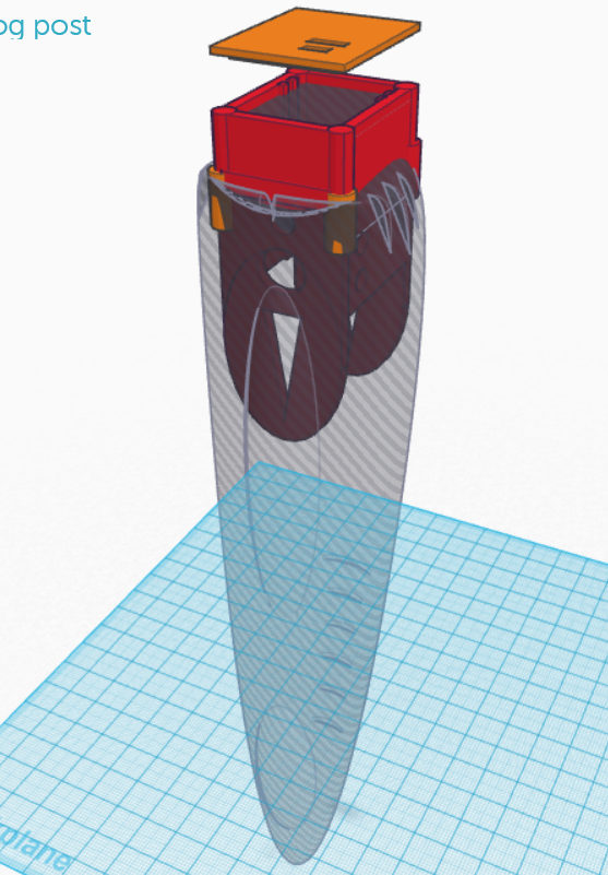
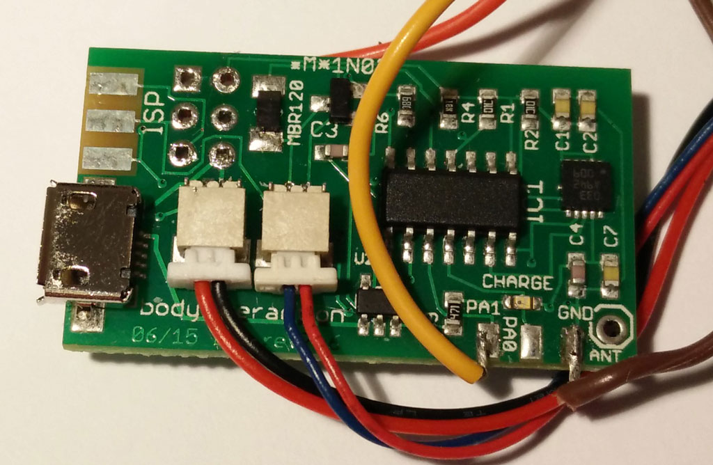
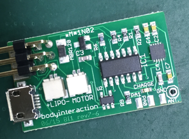
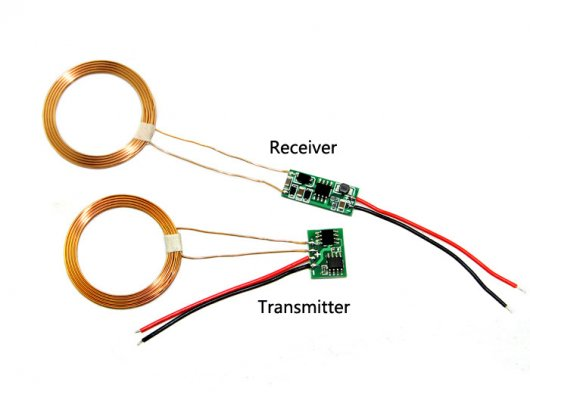
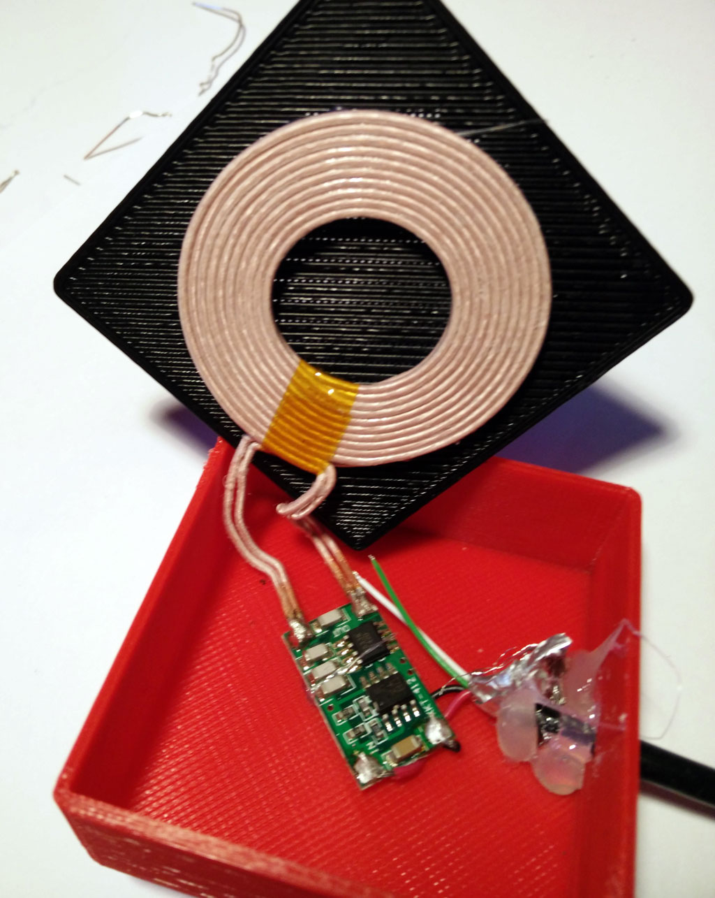
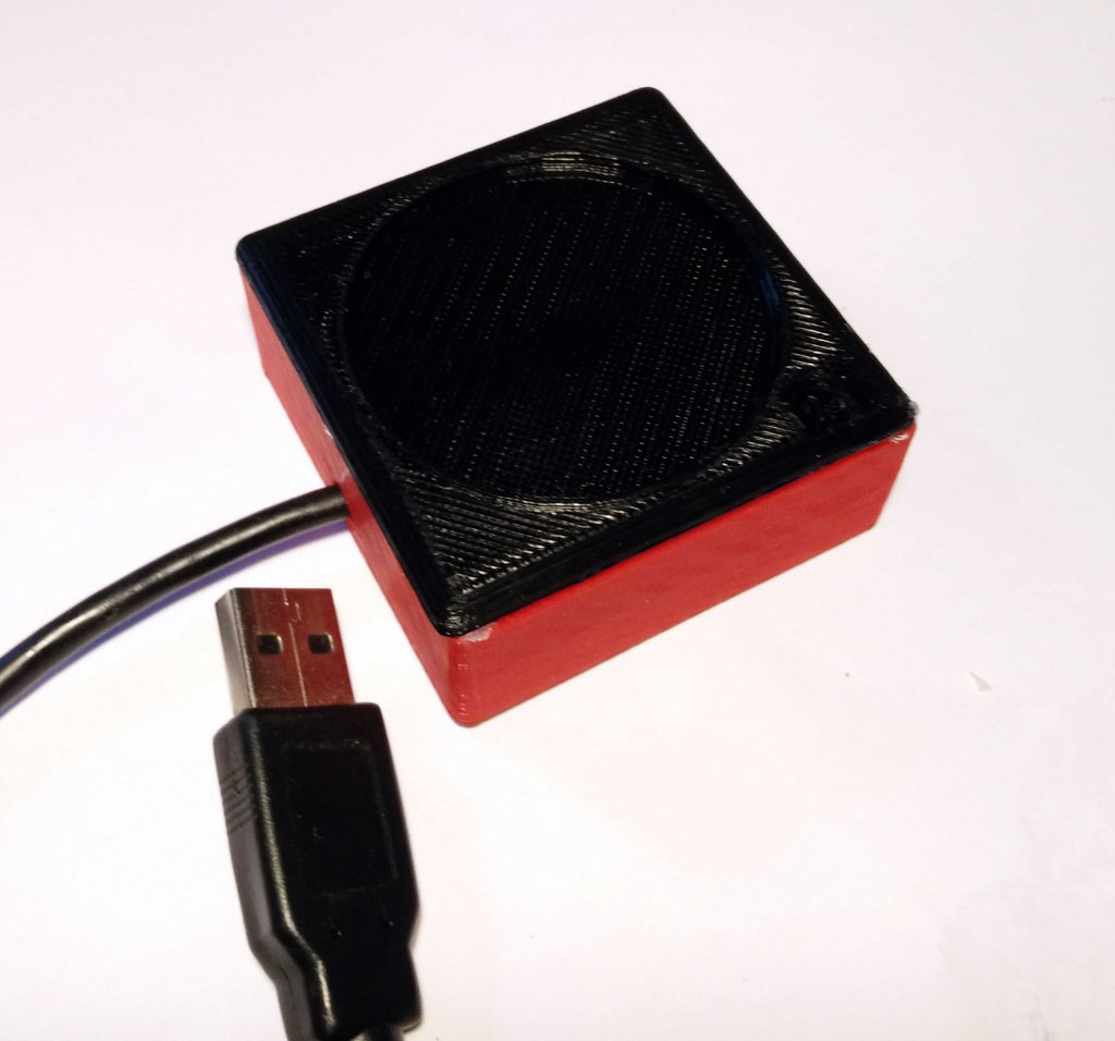
We made a DIY silicone molded vibrator (see here, here and here) using the Arduino compatible body interaction vibrator development board and a wireless charging module. Now we need a charging station where you can put your vibrator for battery charging.

We need a simple box for the wireless charging sender (transmitter) module and the coil. In addition we need a USB cable which we will cut though and connect to the charging module.

It is important to keep the distance between sender and receiver coil as small as possible. The larger the distance is the less power will be transmitted. Therefore the plate where you put the vibrator must be very thin. There are different modules available.


What do you need?

  • A USB cable
  • Wireless charging sender (transmitter) eg. from Seeed Studio, 5V input. The sender (transmitter) will be placed in the charging station. The receiver module will be part of the vibrator. There are different modules available. Look for a 5V input module.seeedwirelesscharging

Instructions:

A. Print out part A and B. Download STL files (zip file)

charging_station_02_final


B. Cut a USB cable. Plug the cable through the hole of form B.

C. Now connect the USB wires with the sender module. Solder the red wire to the (+) pad on the wireless charging sender. Solder the black wire to the (-) pad.

charging-cable-through-and-USB-cable-soldering-to-board

D. Glue the sender board on the bottom of the red form. Put some glue on the cable to fix it. We used hot glue.

charging-board-and-cable-glued

E. Now glue the black form and the sender coil together. We used simple “UHU”-like glue. If the distance between coil and form is too large the charging could be rather slow. So don’t use too much glue.

charging-coil-glued

F. Now put together both parts. Again we used a simple glue.

charging-station-complet-with-USB-cable

G. Insert the USB connector to your PC or any other source. Now the vibrator should be charged which is indicated by an orange LED.

charging-station-in-action-with-body-interaction-vibrator-so-much-balls
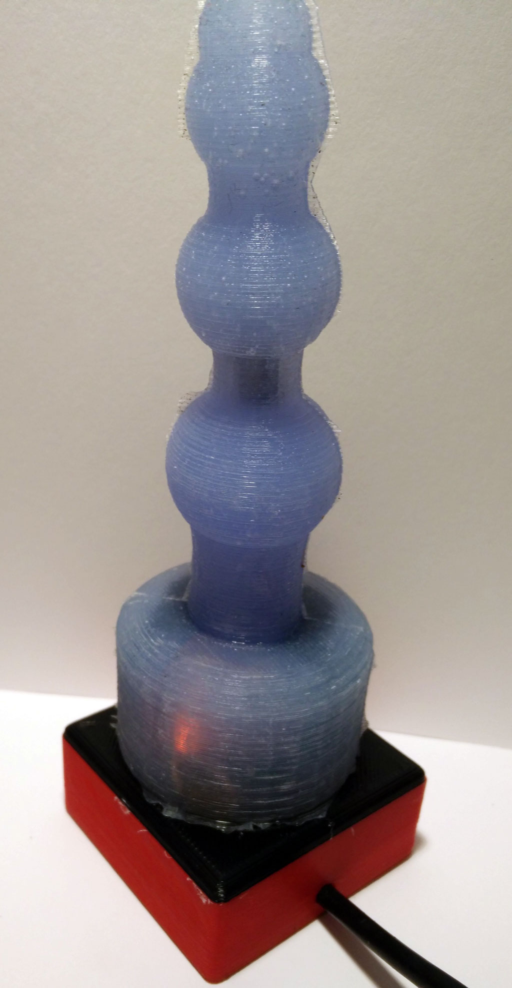
Ready! Have fun with your collection of wireless DIY Arduino-compatible vibrators.


Download STL files (zip file)

All files at Thingiverse: http://www.thingiverse.com/thing:1488428

Tinker and share with Tinkercad:

Part A https://tinkercad.com/things/ijyPmLD1B9e

Part B https://tinkercad.com/things/emWnXUkiH1J

New fusion 3d printed and silicone molded vibrator

fusion tinkercadThis is the initial design. The round curved form will be in silicone with vibration motor within (vibration motor not shown on sketch). The red part is 3d printed. It is the enclosure for the body interaction vibrator development board and LiPo battery. You can plug-in the Micro USB connector for battery charging. In addition there is an on/off switch e.g. for travelling.

Connecting a servo motor – move your vibrator

The body interaction vibrator development board can be connected with additional sensors and actuators. In this post we show how to connect a servo motor. A servo motor can adjust its shaft to be positioned in varies angles. We use a inexpensive SG92R servo which can be positioned in any position between 0° and 180°.

servo-birdNow we can build eg. a linear actuator which could be useful for sex toys. If you have a 3d printer you can build your linear actuator and fix the servo motor. You can download the design here.

servo-from-top

Connecting servo motor and body interaction vibrator development board

The servo motor has 3 wires: ground (-) (black or brown wire), power (+) (red wire) and control (yellow or orange).

servo connection 2pcb-bottomConnect the (+) wire to the body interaction board. You can use the pad on the bottom side as shown on the image.

servo pcb layoutservo-pcb-from-topThen turn the board around to the top side. Now you can solder the black wire to the “GND” (ground) pad. Then solder the orange or yellow control wire to the leftmost pad “PA1”.

Programming the servo motor

The standard Arduino servo library will not work on the body interaction board. But you can use the TinyServo library. Download the library as *.zip file  here or here and read the forum post.

Go into the Arduino library manager and include the ZIP file. Please restart Arduino.

The following script attaches the servo motor and shows how to control it.

// servo control with the body interaction development board using the TinyServo library
// -- adaption of the demo script by
// tylernt@gmail.com's ATTiny Hardware Timer Assisted Servo Library v1.0 20-Nov-13
// http://forum.arduino.cc/index.php?action=dlattach;topic=198337.0;attach=71790

#include <TinyServo.h>
const byte SERVOS = 1; // number of servos is 1
const byte servoPin[SERVOS] = { 7 }; // servo is connected to PA1 which is pin 7
#define SERVO 0 // our servo is given the name "SERVO"

void setup() {
  setupServos();
}

void loop() {
  delay(1000);
  moveServo(SERVO, 180); // move servo to 180°
  delay(1000);
  moveServo(SERVO, 0); // move servo to 0
  delay(1000);
  for (int i = 0; i <= 180; i++) {
    moveServo(SERVO, i); // move servo from 0° to 180° in 1° steps
    delay(50);
  }
  moveServo(SERVO, 0); // move servo to 0°
  delay(1000);
}


Programming Tutorial part 4: Sinus

Nervous Optic by Ben Felten, CC BY-ND 2.0

Nervous Optic by Ben Felten, CC BY-ND 2.0

In tutorial 3 – “ramps” we learned how to repeat instructions again and again using the for statement. In this tutorial we need the for loop again, bur instead of changing the motor speed by a constant value we want a more dynamic behavior. Therefore we use the sinus function – a classical pattern used for controlling vibrators.

Here is a straight forward approach:

for (float i = 0; i < 20000; i = i + 0.05) {
  analogWrite(motor, (sin(i)); //motor speed set to sin(i) 
} 
delay(20); 

We are changing the variable i in small steps of 0.05. So the variable i will become 0, 0.05, 0.1, 0.15, 0,2 … and so on.

But this doesn’t work. Let’s have a look at the sinus function. Just use the google search and type in “sin(x)”. You will see  the following curve:

sin(x) in google

There are two problems:

  • There are values below 0 (on the vertical or y-axis). If the value is 0 or below 0 the motor is off.
  • The maximal value is 1. But  we need values between the minimal motor speed (around 40) and the maximal speed (always 255).

You can try to adjust the function and visualize it with google search. Maybe you will discover an interesting variant of the sinus curve.

We use the following function:

(sin(x)+1) 0.5 * (maximal motor speed – minimal motor speed)) + minimal motor speed

  • Sin(x)+1: add 1 to get positive values only between 0 and 2 instead of -1 and 1.
  • Multiply by 0.5: get values between 0 an 1 instead 0 and 2
  • Multiply with maximal motor speed  (255) – minimal motor speed (40): values are now between 0 and 215
  • Add minimal speed: values are between 40 and 255. So the motor will always be on.


google_sin

This is the script. Please have a look at tutorial 2 if you don’t know how to upload the script.

 // www.bodyinteraction.com tutorial sinus 
int motor = 3; 
int minimal_motorspeed = 50; 

void setup() { 
  pinMode(motor, OUTPUT); 
} 
void loop() { 
  for (float i = 0; i < 20000; i = i + 0.05) { 
    analogWrite(motor, ((sin(i) + 1) * 0.5 * 215) + 40); 
    delay(5); 
  } 
} 

If you want to slow down the changes in the motor speed change delay(5) and take larger values.

Go back to tutorial 3: ramps

Programming the body interaction 1 (BI) part 2

Reading the accelerometer data

The BI has built in the accelerometer Bosch BMA020. The BMA020 is a 3-axis accelerometer and reads acceleration data in X, Y and Z direction. The accelerometer is used to control the operation of the BI. It captures changes in movement eg. slowing, speed up, change of direction. Steady movement can not be captured. Nevertheless it is possible to calculate the orientation of the BI eg. upright or downright.

To read out the data we use the JeeLib – a great library we will use to control other devices and read out sensors (read here how to install). The library must be included, add:

#include <JeeLib.h>

In JeeLib the accelerometer is called GravityPlug. It is not connected to a pin directly (as the vibration motor). Instead it is connected to the I2C bus, but at this point ignore the details. Just add:

PortI2C myBus (1);
GravityPlug sensor (myBus);

Now we can read out the accelerometer using the name “sensor”.

Now we want to read out the sensor. This is done by adding “.getAxes()” to “sensor”. But before we declare a new variable called p, where we the acceleration in X-, Y- and Z-axis is stored:

const int* p = sensor.getAxes();

The acceleration in x-direction is stored in p[0], y-direction in p[1] and z-direction in p[2].

p[0], p[1] and p[2] are integers. When there is no acceleration (eg. the BI is not moved) the value would be approx 0. If you move it horizontally to the right it will return positive values. If you move it horizontal to the left it will return negative values. (Could be vice versa, it depends on the orientation of the accelerometer).

We introduce 3 new variables x, y and z for storing the values:

int x,y,z;

As we are not interested in the direction of the acceleration we convert negative values to positives. This is known as the absolute value and is computed with the function abs(), see: https://www.arduino.cc/en/Reference/Abs

x = abs(p[0]); 
y = abs(p[1]); 
z = abs(p[2]);

We also introduce a further variable called “threshold”. Only values above a given threshold will change the behaviour of the vibration motor. This is useful to ignore the gravity which influences at least of the axises.

int threshold = 250;

Now we put everything together. The script should start the vibration motor if there is acceleration either in x, y or z direction above a threshold. Otherwise the motor is off.

#include JeeLib.h;
PortI2C myBus (1);
GravityPlug sensor (myBus);

int motor = 3;
int threshold = 100;
int x, y, z;

void setup() {
 pinMode(motor, OUTPUT);
}

void loop() {
  const int* p = sensor.getAxes();
  x = abs(p[0]);
  y = abs(p[1]);
  z = abs(p[2]);
  analogWrite(motor, 0); //motor off
  if (x &amp;gt; threshold || y &amp;gt; threshold || z &amp;gt; threshold) {
    analogWrite(motor, 255); //motor on
 }
 delay(2000);  // wait for 2 second
}

Let’s take a further look at the loop. Every time when the instruction in the loop are executed, the sensor will be read out. The absolute values are stored in x, y and z by using the abs() function. Then the motor is set off.

The following statement

analogWrite(motor, 255);

will turn the motor on if the following condition is true:

(x > threshold || y > threshold || z > threshold)

The condition is true when either x > threshold or y > threshold or z > threshold. You can read “||” as logical or. Read more about the if function and boolean operators (or, and, not).

Finally a delay functions stops further processing for 2 seconds. Then the loop will be executed again, starting to read out the accelerometer values.

In depth example of reading the BMA020:

http://playground.arduino.cc/Main/SoftwareI2CLibrary

Jeelib GravityPlug  – how to read out the BMA020 with the JeeLib library.

http://jeelabs.org/2010/03/22/gravity-plug/

More about Acceleration and Gyros and how to calculate the orientation:

http://www.instructables.com/id/Accelerometer-Gyro-Tutorial/


Copy the source code (script) into an Arduino window. Then click compile . If everything is ok you get the message done compiling. sucessful compiling

Then upload the code to the body interaction 1. If everything is ok you get the message done uploading. You can ignore the warnings. done uploadingBut if you don’t get the done uploading message something went wrong. in this case read the following post:

https://bodyinteraction.com/2016/01/08/get-started-with-arduino-1-6-7-and-windows-10/

Go to the next tutorial (part 3): ramps

Programming the body interaction 1 (BI) – part 1

Controlling the vibration motor

The vibration motor is an analog device. You can control the vibration on a scale between 0 and 255. If you set the vibration to 0 the motor is off, if you set the vibration to 255 the motor will be at full speed.

Good vibrations Tokyo by Kevin Dooley, CC BY 2.0

Good vibrations Tokyo by Kevin Dooley, CC BY 2.0

The motor is connected to a pin of the controller (“ATtiny84”), the heart of the BI. Every pin has a number and the motor is always connected to pin 3.

on off chartNow we can start with the first script (or program). The script will set the motor to full speed for one second. Then the motor will be off for 1 second. And this will be repeated infinite.


Here is the complete script:

int motor=3;
void setup() {
  pinMode(motor, OUTPUT);
}

void loop() {
  analogWrite(motor, 255); //motor on
  delay(1000);  // wait for 1 second
  analogWrite(motor, 0); //motor off
  delay(1000);
}

Now the script is explained line by line:

int motor=3;

First we declare a variable called “motor” and assign the value 3. The variable is of type int (integer) which is used to store a number. Now we could use “motor” instead of “3” whenever we want to control the vibration motor – this will help us to understand and debug our script.

void setup() {
  …
}

This is function which is part of every Arduino script. It is called setup and well be executed at first and only once.

pinMode(motor, OUTPUT);

Each pin can be in INPUT or OUTPUT mode. In input mode sensor data can read, in output mode a motor or a LED can be controlled. We set the motor pin to OUTPUT.

void loop() {
  …
}

In the function loop we put all the instructions which should be carried out. When all instructions are done the script doesn’t stop but starts again. Therefore the loop will be repeated infinite.

analogWrite(motor, 255);

The motor is set to full speed (255).

delay(1000);

The delay function stops all processing for 1000 milliseconds. 1000 millisecond are 1 second.

analogWrite(motor, 0);

Then motor is set off (0). In the second part of the tutorial uploading of the script to the body interaction 1 is explained.

More:

https://www.arduino.cc/en/Tutorial/Foundations

Read part 2: the accelerometer

Get started with Arduino 1.6.7 and Windows 10

Thanks to christmas I am the owner of a new Windows 10 notebook. So I experienced the trouble other user encounter when the use the ATtiny microcontroller the first time.

I wrote a new how-to for the installation of Arduino 1.6.7. Although it takes some time to configure all options, everything can be done within Arduino 1.6.7 (No replacing and moving of files is necessary.)

sucessful compiling

The how-to describes the necessary steps:

  1. Installation of an ATtiny core (thanks to the new core from Spence Konde installation is much easier)
  2. Installation of the JeeLib
  3. Configuration (programmer etc.)

Driver installation (Windows only)

Another frustating aspect is the installation of the driver for the USBtinyISP. The USBtinyISP is needed to connect your Windows computer and the body interaction development board. The connect your computer how-to is now improved. If you use Linux or a Mac there is no driver needed.

French article about comingle, master-beta kit and bodyinteraction

Tu sais où tu peux le mettre, ton Arduino ?

Do you know where you can put your Arduino? –  Francois Mocq reports about three Arduino vibrator projects: comingle, master-beta kit and body interaction. Even more interesting he queries whether Arduino or Raspberry Pi is the right platform.

raspberry_pi_logo_rgb_552x650-212x250Raspberry Pi offers much more computing power and connectivity, eg. you could add a camera, do video processing and add more hardware.

On the other hand programming can be more complex and it may take more time to run you first script.


And there are more platforms out there like the very cheap ESP 8266 module with the NodeMCU software. The ESP8266 can connect directly with the internet via wi-fi.


Follow the discussion

Review of vibrator development boards

Designing your own sex toys with advanced technology is becoming popular. Although the community is still very small the interest is rising. In this article we will introduce for open source vibrator development boards including our body interaction 1. We will see how the design of the development boards determines the design space – the possibilities of sex toys which can be realized.

Comingle may be the most successful open source sex toy company. They invented the Mod – an Arduino based vibrator with 3 vibration motors. They also offer the Dilduino – a development board based on the Atmel ATmega342U4 (similar to the Arduino Micro). The board can drive 3 vibration motors. They have developed a great library for programming vibration pattern (“OS sex“). You can use arbitrary function like sinus or cosinus to define pattern. You can upload programs via the USB connection, but there is no wireless radio or WiFi connection on board. The board lacks battery charging support, so you need external power. As the board is quite large it is only suitable for larger toys. Available at Tindie.
Pro: supports 3 motors, full Arduino compatible, great library, superb tutorials
Cons: no wireless connectivity, no battery charger, quite large for being part of a sex toy

pen15_smallPen 15 shield is a shield for the Arduino Uno.  So you need an Arduino Uno in addition to the shield. The shield must be connected to the Arduino board. It has one driver for a vibration motor. This pioneer work was announced in 2011, but it is probably not available any more. The price is quite low. There is no battery charging option and it is very large compared to the other boards.
Pro: full Arduino compatible
Cons: no wireless connectivity, no battery charger, too large to be part of a sex toy

Master Beta Kit from Orgasmatronic Inc. is another shield for the Arduino Uno. It can control two vibration motors. The power source for the vibration motors could be different though you may control motors with different input voltages. Easy assembling and support with online tutorials.

Pro: full Arduino compatible, different motor input voltage
Cons: no wireless connectivity, no battery charger, too large to be part of a sex toy

Assembled boardThe body interaction development board can drive one motor. It has a LiPo battery charging option. It can be controlled by motion – a 3-axis accelerometer is build in. Using motion you can control the vibrator – no need for further peripherals like switches or slider for controlling the vibration speed. The main advantage is the wireless radio especially if you like to use more than one sex toy at once. You can transmit data between your toys, control your toys or even synchronize them. The form factor is very small, though it can be part of a small toy. As the board is only 20x36mm there is not much space for further functionalities: It has no serial interface. To upload a program you need an ISP programmer (eg USBtinyISP). And it uses a microcontroller from the ATMEL ATtiny series. Although the tiny microcontrollers are getting more and more popular they have some disadvantage compared to the standard ATmega328p: There is not much memory on the chip (8K instead 32K), some libraries may not work, less I/O ports. Available at Tindie.
Pro: small form factor, LiPo battery charger included, wireless radio, motion tracking
Cons: some libraries don’t work, programmer needed for uploading programs

263867448_047fe6a73f_m

From Gideon, Paris, City of Love, https://flic.kr/p/pjoAL License: CC BY 2.0 https://creativecommons.org/licenses/by/2.0/

Most probably we will see more boards arrive and we hope that there are Open Source, too. But for a breakthrough for open source DIY sex toys an open standard would be helpful like the Arduino helped physical computing becoming popular for nerds, SIGs,  artists, scientists, hobbyist, industry!
But open source sex toys are not only a technical endeavour. It is about our relation to love, sex, partnership, about taking responsibility. Open sex toys are about getting a deep and well-founded understanding of our personal sexuality and the sexuality of our loved ones.


%d bloggers like this: