Tag: programming

Connecting a servo motor – move your vibrator

The body interaction vibrator development board can be connected with additional sensors and actuators. In this post we show how to connect a servo motor. A servo motor can adjust its shaft to be positioned in varies angles. We use a inexpensive SG92R servo which can be positioned in any position between 0° and 180°.

servo-bird
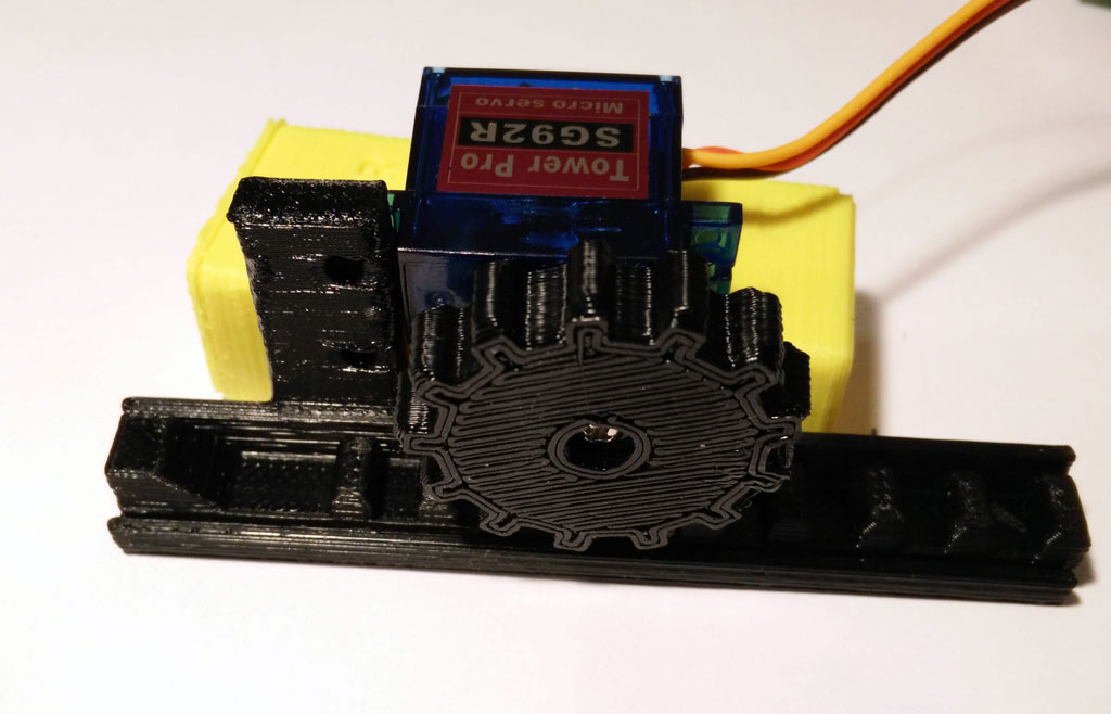
Now we can build eg. a linear actuator which could be useful for sex toys. If you have a 3d printer you can build your linear actuator and fix the servo motor. You can download the design here.

servo-from-top

Connecting servo motor and body interaction vibrator development board

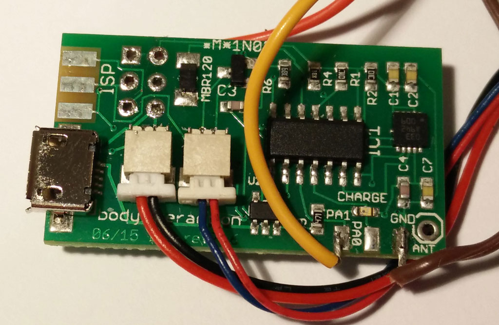
The servo motor has 3 wires: ground (-) (black or brown wire), power (+) (red wire) and control (yellow or orange).

servo connection 2pcb-bottom
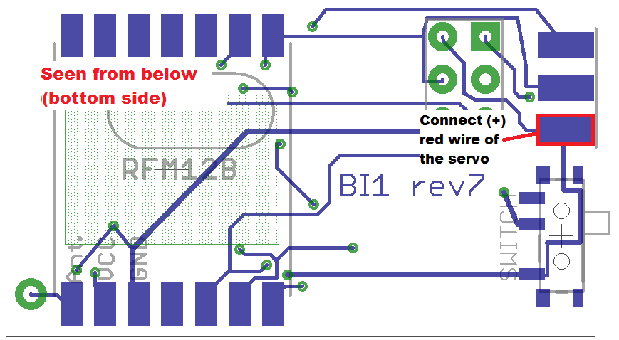
Connect the (+) wire to the body interaction board. You can use the pad on the bottom side as shown on the image.

servo pcb layoutservo-pcb-from-top
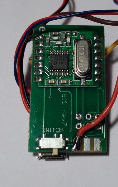
Then turn the board around to the top side. Now you can solder the black wire to the “GND” (ground) pad. Then solder the orange or yellow control wire to the leftmost pad “PA1”.

Programming the servo motor

The standard Arduino servo library will not work on the body interaction board. But you can use the TinyServo library. Download the library as *.zip file  here or here and read the forum post.

Go into the Arduino library manager and include the ZIP file. Please restart Arduino.

The following script attaches the servo motor and shows how to control it.

// servo control with the body interaction development board using the TinyServo library
// -- adaption of the demo script by
// tylernt@gmail.com's ATTiny Hardware Timer Assisted Servo Library v1.0 20-Nov-13
// http://forum.arduino.cc/index.php?action=dlattach;topic=198337.0;attach=71790

#include <TinyServo.h>
const byte SERVOS = 1; // number of servos is 1
const byte servoPin[SERVOS] = { 7 }; // servo is connected to PA1 which is pin 7
#define SERVO 0 // our servo is given the name "SERVO"

void setup() {
  setupServos();
}

void loop() {
  delay(1000);
  moveServo(SERVO, 180); // move servo to 180°
  delay(1000);
  moveServo(SERVO, 0); // move servo to 0
  delay(1000);
  for (int i = 0; i <= 180; i++) {
    moveServo(SERVO, i); // move servo from 0° to 180° in 1° steps
    delay(50);
  }
  moveServo(SERVO, 0); // move servo to 0°
  delay(1000);
}


Programming Tutorial part 4: Sinus

Nervous Optic by Ben Felten, CC BY-ND 2.0

Nervous Optic by Ben Felten, CC BY-ND 2.0

In tutorial 3 – “ramps” we learned how to repeat instructions again and again using the for statement. In this tutorial we need the for loop again, bur instead of changing the motor speed by a constant value we want a more dynamic behavior. Therefore we use the sinus function – a classical pattern used for controlling vibrators.

Here is a straight forward approach:

for (float i = 0; i < 20000; i = i + 0.05) {
  analogWrite(motor, (sin(i)); //motor speed set to sin(i) 
} 
delay(20); 

We are changing the variable i in small steps of 0.05. So the variable i will become 0, 0.05, 0.1, 0.15, 0,2 … and so on.

But this doesn’t work. Let’s have a look at the sinus function. Just use the google search and type in “sin(x)”. You will see  the following curve:

sin(x) in google

There are two problems:

  • There are values below 0 (on the vertical or y-axis). If the value is 0 or below 0 the motor is off.
  • The maximal value is 1. But  we need values between the minimal motor speed (around 40) and the maximal speed (always 255).

You can try to adjust the function and visualize it with google search. Maybe you will discover an interesting variant of the sinus curve.

We use the following function:

(sin(x)+1) 0.5 * (maximal motor speed – minimal motor speed)) + minimal motor speed

  • Sin(x)+1: add 1 to get positive values only between 0 and 2 instead of -1 and 1.
  • Multiply by 0.5: get values between 0 an 1 instead 0 and 2
  • Multiply with maximal motor speed  (255) – minimal motor speed (40): values are now between 0 and 215
  • Add minimal speed: values are between 40 and 255. So the motor will always be on.


google_sin

This is the script. Please have a look at tutorial 2 if you don’t know how to upload the script.

 // www.bodyinteraction.com tutorial sinus 
int motor = 3; 
int minimal_motorspeed = 50; 

void setup() { 
  pinMode(motor, OUTPUT); 
} 
void loop() { 
  for (float i = 0; i < 20000; i = i + 0.05) { 
    analogWrite(motor, ((sin(i) + 1) * 0.5 * 215) + 40); 
    delay(5); 
  } 
} 

If you want to slow down the changes in the motor speed change delay(5) and take larger values.

Go back to tutorial 3: ramps

Programming the body interaction 1 – part 3 – ramps

Ramps

by darkday, CC BY 2.0

“Milf Ramp attack” by darkday, CC BY 2.0

In this tutorial the continuous change of the vibration motor speed is regarded. Typical vibrator pattern are ramps. They start at a given value. Then the motor speed is continuously changed. The values could be increasing or decreasing.

In our example we have two ramps.

  • Increasing ramp: It starts with the minimal motor speed (40). The vibration is slowly increased up to maximal speed (255).
  • Decreasing ramp: It starts with maximal motor speed and decreases very fast until minimal motor speed is reached.


ramps

We will achieve this by using the for statement.

for (int i=minimal_motorspeed; i &lt;=255; i++) {
  analogWrite(motor, i);
  delay(10); // wait for 1/100 second
}

The code after the for statement will be repeated so long a condition remains true.

  • int i =minimal_motorspeed: a new local variable i is introduced and given the value of minimal_motorspeed (40)
  • i <= 255: this is the condition – until the variable is below or equal 255 the code will be executed
  • i++: each time the code is executed the variable i will be increased by 1

The values of i are 40, 41, 42, 43, … , 255. We use the variable i to change the motor speed. The speed of the motor will be changed at each iteration. So the motor speed will be set to 40 (which is the minimal speed), 41, 42, …, 255 using the following statement:

analogWrite(motor, i);

The delay statement changes the pitch of the ramp. If the delay time is high the pitch will be low:

delay(10);


The following code will realize the function visualized above. You can change the pitch by adjusting the delay time.

// www.bodyinteraction.com tutorial ramp
int motor=3;
int minimal_motorspeed=40;
void setup() {
  pinMode(motor, OUTPUT);
}
void loop() {
  for (int i=minimal_motorspeed; i &lt;=255; i++) {
    analogWrite(motor, i);
    delay(10);
  }
  for (int i=255; i &gt; minimal_motorspeed; i--) {
    analogWrite(motor, i);
    delay(2);
  }
  analogWrite(motor, 0); //motor off
  delay(1000);
}

Copy the code to Arduino and try out. In tutorial 2 it is explained how to upload the code to the body interaction 1.

Next tutorial: Classical vibration pattern – the sinus curve

Go back to tutorial acceleration

Danniel Ramirez, CC BY 2.0

Ramp to the beach by Danniel Ramirez, CC BY 2.0

Programming the body interaction 1 (BI) part 2

Reading the accelerometer data

The BI has built in the accelerometer Bosch BMA020. The BMA020 is a 3-axis accelerometer and reads acceleration data in X, Y and Z direction. The accelerometer is used to control the operation of the BI. It captures changes in movement eg. slowing, speed up, change of direction. Steady movement can not be captured. Nevertheless it is possible to calculate the orientation of the BI eg. upright or downright.

To read out the data we use the JeeLib – a great library we will use to control other devices and read out sensors (read here how to install). The library must be included, add:

#include <JeeLib.h>

In JeeLib the accelerometer is called GravityPlug. It is not connected to a pin directly (as the vibration motor). Instead it is connected to the I2C bus, but at this point ignore the details. Just add:

PortI2C myBus (1);
GravityPlug sensor (myBus);

Now we can read out the accelerometer using the name “sensor”.

Now we want to read out the sensor. This is done by adding “.getAxes()” to “sensor”. But before we declare a new variable called p, where we the acceleration in X-, Y- and Z-axis is stored:

const int* p = sensor.getAxes();

The acceleration in x-direction is stored in p[0], y-direction in p[1] and z-direction in p[2].

p[0], p[1] and p[2] are integers. When there is no acceleration (eg. the BI is not moved) the value would be approx 0. If you move it horizontally to the right it will return positive values. If you move it horizontal to the left it will return negative values. (Could be vice versa, it depends on the orientation of the accelerometer).

We introduce 3 new variables x, y and z for storing the values:

int x,y,z;

As we are not interested in the direction of the acceleration we convert negative values to positives. This is known as the absolute value and is computed with the function abs(), see: https://www.arduino.cc/en/Reference/Abs

x = abs(p[0]); 
y = abs(p[1]); 
z = abs(p[2]);

We also introduce a further variable called “threshold”. Only values above a given threshold will change the behaviour of the vibration motor. This is useful to ignore the gravity which influences at least of the axises.

int threshold = 250;

Now we put everything together. The script should start the vibration motor if there is acceleration either in x, y or z direction above a threshold. Otherwise the motor is off.

#include JeeLib.h;
PortI2C myBus (1);
GravityPlug sensor (myBus);

int motor = 3;
int threshold = 100;
int x, y, z;

void setup() {
 pinMode(motor, OUTPUT);
}

void loop() {
  const int* p = sensor.getAxes();
  x = abs(p[0]);
  y = abs(p[1]);
  z = abs(p[2]);
  analogWrite(motor, 0); //motor off
  if (x &amp;gt; threshold || y &amp;gt; threshold || z &amp;gt; threshold) {
    analogWrite(motor, 255); //motor on
 }
 delay(2000);  // wait for 2 second
}

Let’s take a further look at the loop. Every time when the instruction in the loop are executed, the sensor will be read out. The absolute values are stored in x, y and z by using the abs() function. Then the motor is set off.

The following statement

analogWrite(motor, 255);

will turn the motor on if the following condition is true:

(x > threshold || y > threshold || z > threshold)

The condition is true when either x > threshold or y > threshold or z > threshold. You can read “||” as logical or. Read more about the if function and boolean operators (or, and, not).

Finally a delay functions stops further processing for 2 seconds. Then the loop will be executed again, starting to read out the accelerometer values.

In depth example of reading the BMA020:

http://playground.arduino.cc/Main/SoftwareI2CLibrary

Jeelib GravityPlug  – how to read out the BMA020 with the JeeLib library.

http://jeelabs.org/2010/03/22/gravity-plug/

More about Acceleration and Gyros and how to calculate the orientation:

http://www.instructables.com/id/Accelerometer-Gyro-Tutorial/


Copy the source code (script) into an Arduino window. Then click compile . If everything is ok you get the message done compiling. sucessful compiling

Then upload the code to the body interaction 1. If everything is ok you get the message done uploading. You can ignore the warnings. done uploadingBut if you don’t get the done uploading message something went wrong. in this case read the following post:

https://bodyinteraction.com/2016/01/08/get-started-with-arduino-1-6-7-and-windows-10/

Go to the next tutorial (part 3): ramps

Programming the body interaction 1 (BI) – part 1

Controlling the vibration motor

The vibration motor is an analog device. You can control the vibration on a scale between 0 and 255. If you set the vibration to 0 the motor is off, if you set the vibration to 255 the motor will be at full speed.

Good vibrations Tokyo by Kevin Dooley, CC BY 2.0

Good vibrations Tokyo by Kevin Dooley, CC BY 2.0

The motor is connected to a pin of the controller (“ATtiny84”), the heart of the BI. Every pin has a number and the motor is always connected to pin 3.

on off chartNow we can start with the first script (or program). The script will set the motor to full speed for one second. Then the motor will be off for 1 second. And this will be repeated infinite.


Here is the complete script:

int motor=3;
void setup() {
  pinMode(motor, OUTPUT);
}

void loop() {
  analogWrite(motor, 255); //motor on
  delay(1000);  // wait for 1 second
  analogWrite(motor, 0); //motor off
  delay(1000);
}

Now the script is explained line by line:

int motor=3;

First we declare a variable called “motor” and assign the value 3. The variable is of type int (integer) which is used to store a number. Now we could use “motor” instead of “3” whenever we want to control the vibration motor – this will help us to understand and debug our script.

void setup() {
  …
}

This is function which is part of every Arduino script. It is called setup and well be executed at first and only once.

pinMode(motor, OUTPUT);

Each pin can be in INPUT or OUTPUT mode. In input mode sensor data can read, in output mode a motor or a LED can be controlled. We set the motor pin to OUTPUT.

void loop() {
  …
}

In the function loop we put all the instructions which should be carried out. When all instructions are done the script doesn’t stop but starts again. Therefore the loop will be repeated infinite.

analogWrite(motor, 255);

The motor is set to full speed (255).

delay(1000);

The delay function stops all processing for 1000 milliseconds. 1000 millisecond are 1 second.

analogWrite(motor, 0);

Then motor is set off (0). In the second part of the tutorial uploading of the script to the body interaction 1 is explained.

More:

https://www.arduino.cc/en/Tutorial/Foundations

Read part 2: the accelerometer

Visualize and publish sex toy activity – part 2

In the first how-to we explained how-to upload the data of the body interaction vibrator development board to a database.

Now we want to show you how easy it is to visualize the motion data of one or more body interaction boards. And in the last part of the how-to we set up a webserver. So you can share your activity data with other.

BI activity 3+ HTML

Web form for ploting your sex toy data

What could we learn from this data:

  • how often people use sex toys
  • how long is a typical session
  • motion frequency analysis for orgasm detection

There are manifold application areas for this data:

  • compare (and compete) with others
  • quantify yourself
  • learn more about the quality of sex
  • share benefitable sex toy usage pattern

You could also combine the sex toy data with other fitness data and learn how sex eg. influences your health.

That’s the end of the “record and share sex toy data” series. We would like to know what you think about this. Does it make sense? To complex? Should we develop a body interaction “base station” with a web server? Or would you prefer an app for your smartphone?

Figure: Activity of 3 BI boards over time. Each color represents one BI which has a distinct node ID.

Figure: Activity of 3 BI boards over time. Each color represents one BI which has a distinct node ID.

How a program for the body interaction 1 works

The P5_fin script (program) is the basic Arduino script which demonstrates all functions available:

  • The speed of the vibration motor is controlled by movements.
  • Movement data are sent to other body interaction boards.
  • Vibration strength is adjusted when near by body interaction boards have different speed

BI1 interaction pattern

How it works:

The P5_fin script reads data from the accelerometer. Depending of the measured motion the vibration motor is speed up or slowed down. (Slow motion = reduce vibration motor speed, fast motion = speed up).

When the measured motion changes the motion data are sent out and can be received by other BI1. At the same time this script listen to other body interaction boards which send their motion data to all listening nodes.

CodebenderWithBI script and parametersWhen the measured motion of other body interaction board are different from the motion measured by this script, the vibration motor is adjusted (speed up or slowed down). So two or more body interaction boards can influence each other and synchronize after some time. The documented script is available in codebender. In this how-to the uploading of the script is explained.


Record and share sex toy activity

John Millward showed in his recent study that there is not much knowledge about sex toy usage. By analysing buying behaviour in UK biggest online store he learned a lot about who is interested in which kind of toy (men/woman, single/attached). But who will use the toy which one has bought for what and for how long is still unknown.

Activity of 3 BI boards over time. Each color represents one BI which has a distinct node ID.

Activity of 3 body interaction (BI) vibration development boards over time. Each color represents one BI.

The body interaction vibrator development board recognizes activity (motion) data and sends the data to other boards or to a server. So it is possible to upload the usage data of one or multiple vibrators to a (internet) database.

What could we learn from this data:

  • how often people use sex toys
  • how long is a typical session
  • usage pattern: on your own or with your partner
  • handling of the vibrator
  • motion frequency analysis for orgasm detection

There are manifold application areas for this data:

  • compare (and compete) with others
  • quantify yourself
  • learn more about the quality of sex
  • share benefitable sex toy usage pattern

You could also combine the sex toy data with other fitness data and learn how sex eg. influences your health.

With the body interaction vibrator development board it is easy to upload the data. In this how-to we explain how it is done. In the next blog post we will explain the presentation of sex toy activity plots in the web.

Programming with Codebender

CodebenderWithBI script and parametersCodebender is a great browser-based programming tool. Especially their support for non-standard Arduino platforms like the popular ATtiny microcontrollers is impressive. Before codebender you had to install the actual Arduino software plus the ATtiny core plus compiler updates…

With codebender you select the Arduino core and that’s it. In the new how-to we show you how-to upload a Arduino script to the body interaction 1 (BI1) board. And we present you a script for controlling the  BI1 and how BI1 communicate wireless with one another.

%d bloggers like this: