
Since a few month, I own an Elegoo Mars Resin printer. It has UV LCD screen for “printing” each layer. In addition, I have an Elegoo Mercury Wash & Cure machine for a few weeks. These machines are incredibly affordable, they work and have a high resolution. The print space is rather small (120 (L) x 68 x 155 (H)…
Tag: 3D printed form
Basic Node for the Internet of Sex Toys – part 2: 3d printed form, assembly, molding
 In this series of posts we describe how-to make a vibrating sex toy which is part of the Internet of Things.
part 1: Basic Node for the Internet of Sex Toys
part 2: Molding the Basic Node
part 3: Software for the Basic Node
In part 2 we describe how-to make a mold form for the basic node. We need three forms:
- the mold form which consists of two parts
- the inlay which protects the electronics of the basic node
- a “hanging” for the inlay

We used Tinkercad to construct the parts. The molding form is based on Tinkercad’s banana form. You can edit and share them from your browser:
Inlay: https://tinkercad.com/things/h5fFOBqlmjw
Hanging: https://tinkercad.com/things/jUxc2oAamww
Form: https://tinkercad.com/things/6HS3XScOsCM
Instructions
Print out all forms. The STL files are available at Thingiverse. You might want to use XTC or similar for smoothing the inner part of the mold form.
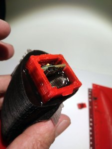
Assembling the Inlay
We use the inlay to protect the electronics.
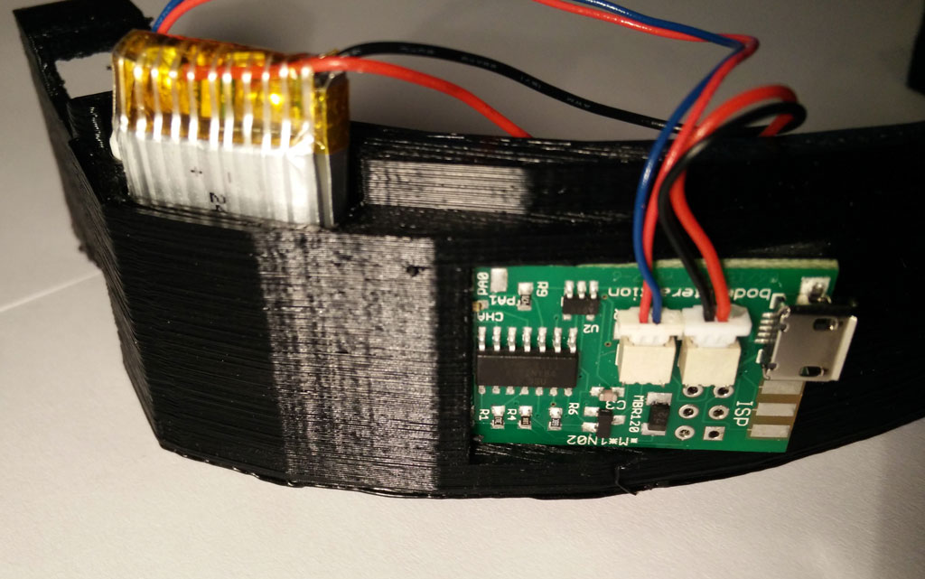
 Simply put the electronics inside so that the upper body of the switch is on the same level as the upper inlay. We use hot glue to fix the basic node.
 Then fix the receiver coil of the wireless charging module on top of the inlay. The next step is to fix the hanging at the inlay.
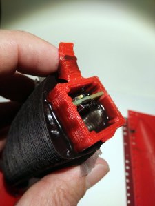
 Now fix the LiPo battery on the bottom side of the inlay using hot glue or similar. Fix the wires. Finally you might fix the wires of the vibration motor next to the middle of the LiPo battery.
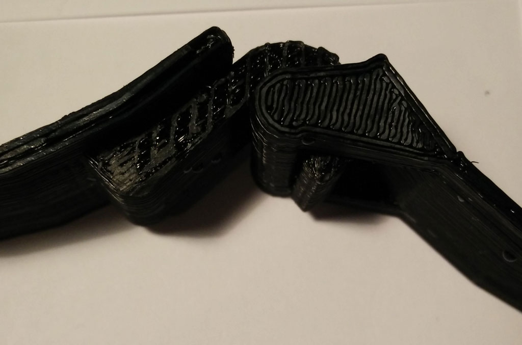
 Use tinkering wire to fix both parts of the molding form.
 Put the inlay in the form. Fix the hanging with a tape or similar. The motors shouldn’t touch the inner part of the form.
 Now prepare the silicone. We use Shore A 45 silicone (approx. 250 ml) from Silikonfabrik.de. It is hard but still a bit flexible. You may add color, too. You have about 10 minutes to stir the silicone and poor it in the form.
After some hours you can remove the form. As you can see there is overhang which make removing the form very hard. The form could break when removing. Better preparation of the form (eg rasping) could improve the results.
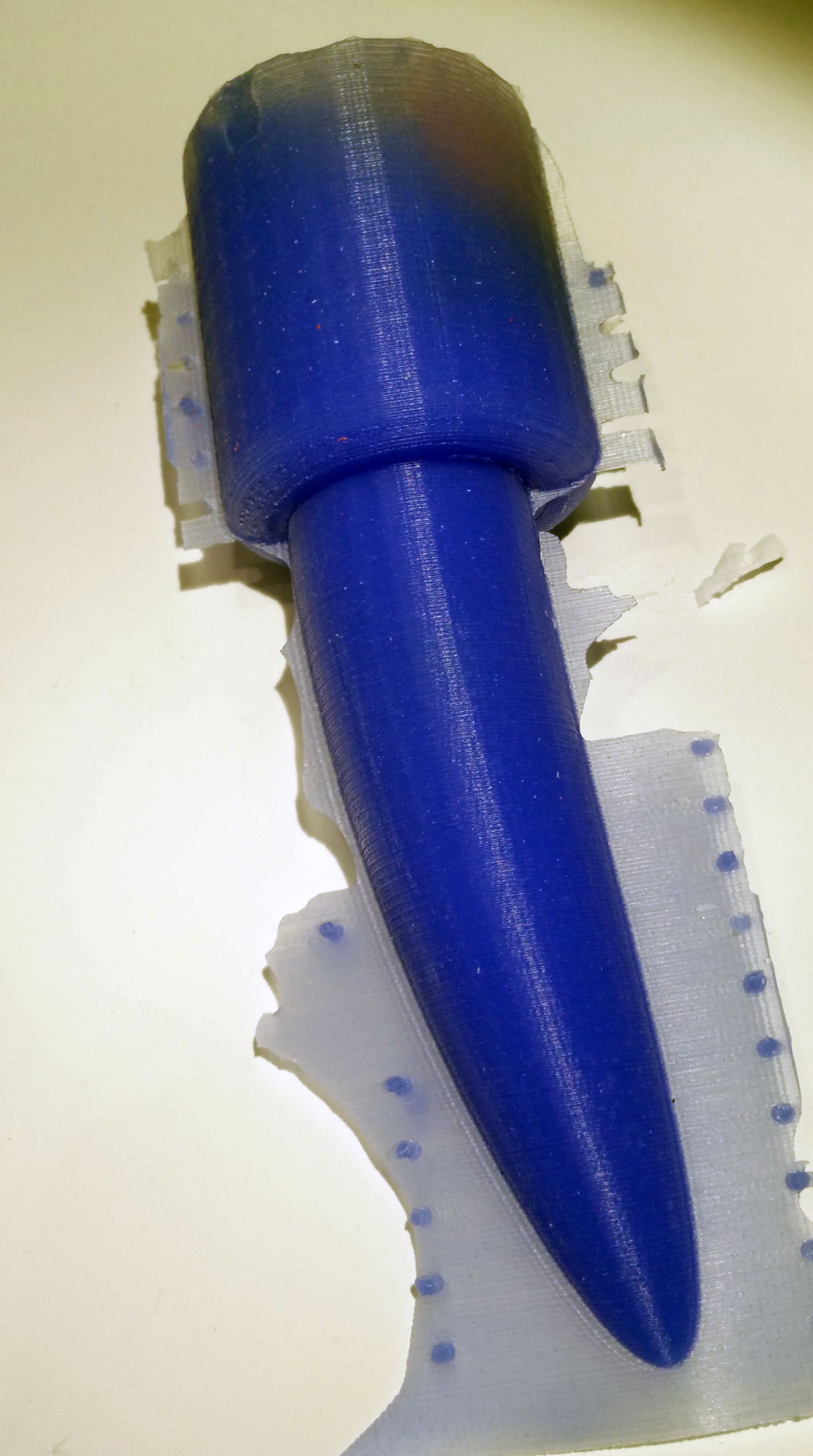
If the blue LED of the Wemos board is still active you were successful.

Now you need a charging station. The construction is shown here. It is also possible to connect the sender (or transmitter) module with a 5V power source (eg. from the USB port). Just put the bottom of the molded basic node on the sender coil.
In the next part we introduce an updated version of the software including over the air update and WiFi management.
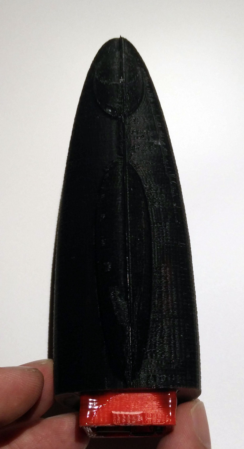
Smooth 3d printed vibrator form for silicone molding
 We started with printing sex toys (see here, here and here), then moved to printing mold forms for sex toys and finally we made sex toys which are partially silicone molded and partially printed. The best results were achieved with printing mold forms and fill them with silicone. But even there we have the problem that the surface isn’t really smooth and that it is hard to clean.
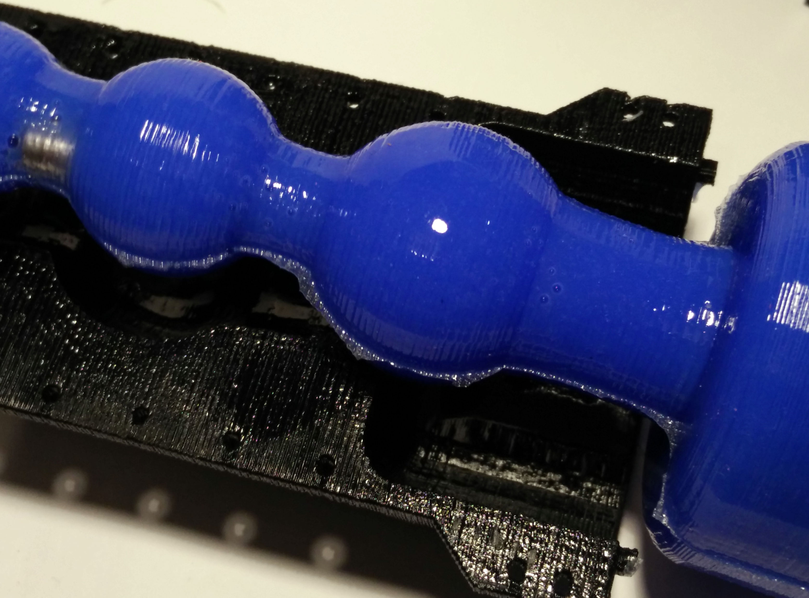
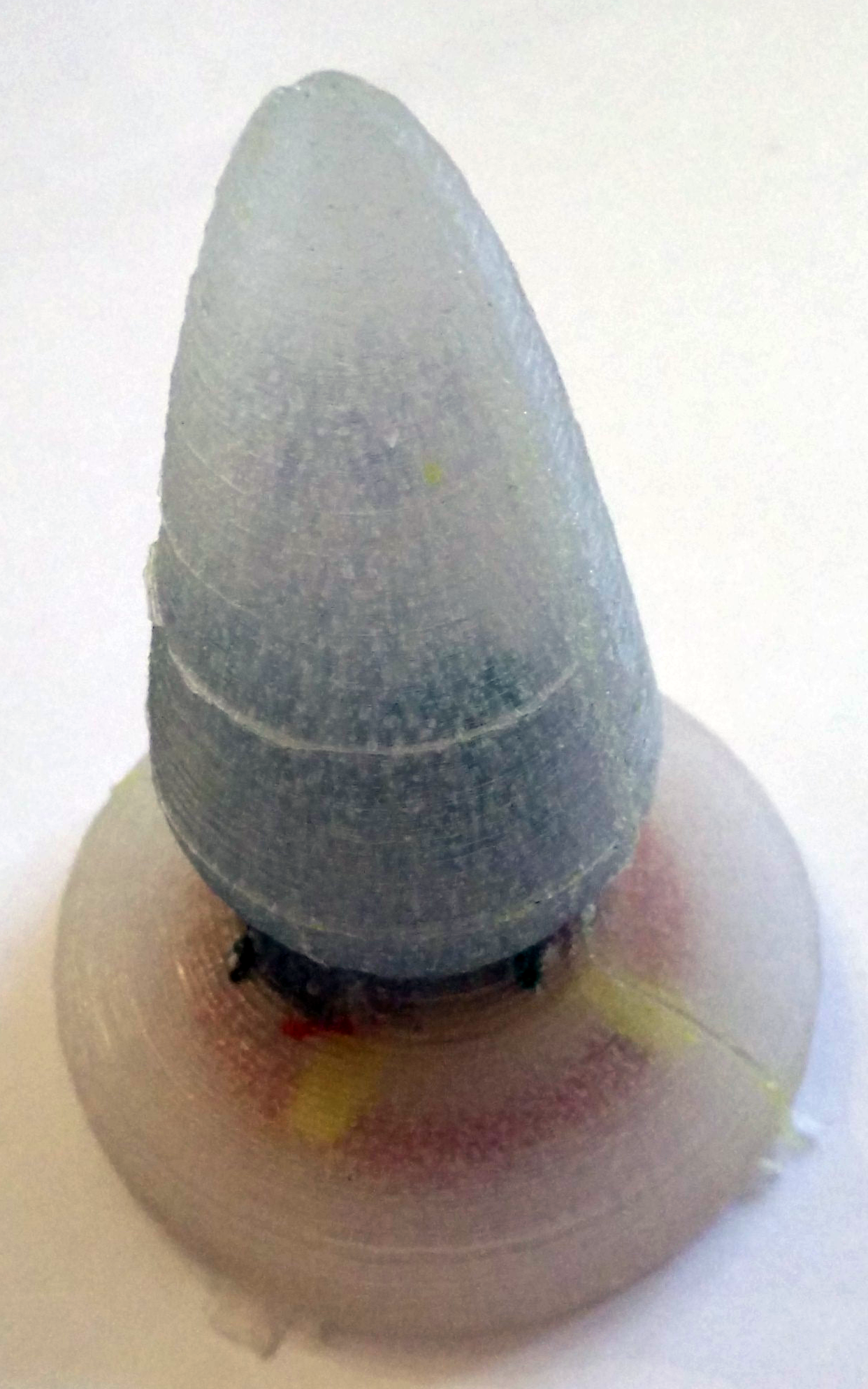
 To overcome this problem we use a 3d print smoothing (XTC 3D) to smooth the surface. Application is very easy. It is like applying a transparent varnish. The results are impressive: The silicone gets a smooth shiny surface.
 But you can still see printer artefacts. To overcome this issue you could apply a thicker layer of XTC-3D. If you use a better printer than my daVinci 1.0 the “staircase effect” shouldn’t be a problem at all. Another problem are tiny – sometimes quite large – air bubbles. To remove this air bubbles you need a vacuum chamber. So it is still not perfect, but it works and looks quite good…
OpenSCAD as silicone molding form generator
 An alternative to 3d-printed sex toys are silicone toys. For making such a sex toy you need a molding form, where you pour in the silicone. If you use Tinkercad to build the form for the balls motive, you may need more than one hour. If you are not experienced in 3d constrcution it may take days. That’s ok and can be fun as you can realize your fantasies step by step.
 But if you want to change a detail or want to resize some parts of it, it will take a long time as you have to unbuilt parts of the form, make changes and then reassemble. Sometimes building from scratch is faster.
In the last blog post we have introduced OpenSCAD to construct a sex toy form. Now we want to build a hull for the sex toy for overmolding.
The basic idea is very simple:
- Generate two forms. The smaller one has the size of the sex toy you want to make. The larger one will be the form where you pour in the silicone.
- Than use the OpenSCAD difference command which “subtracts” or cuts out the smaller form from the larger form.
But it is more complicated:
- You have to include a frame otherwise the form would fall over.
- You need two forms (A and b) so you could open the form after molding.
- Both forms must be fastened together when molding. Therefore you need holes for tinkering wire.
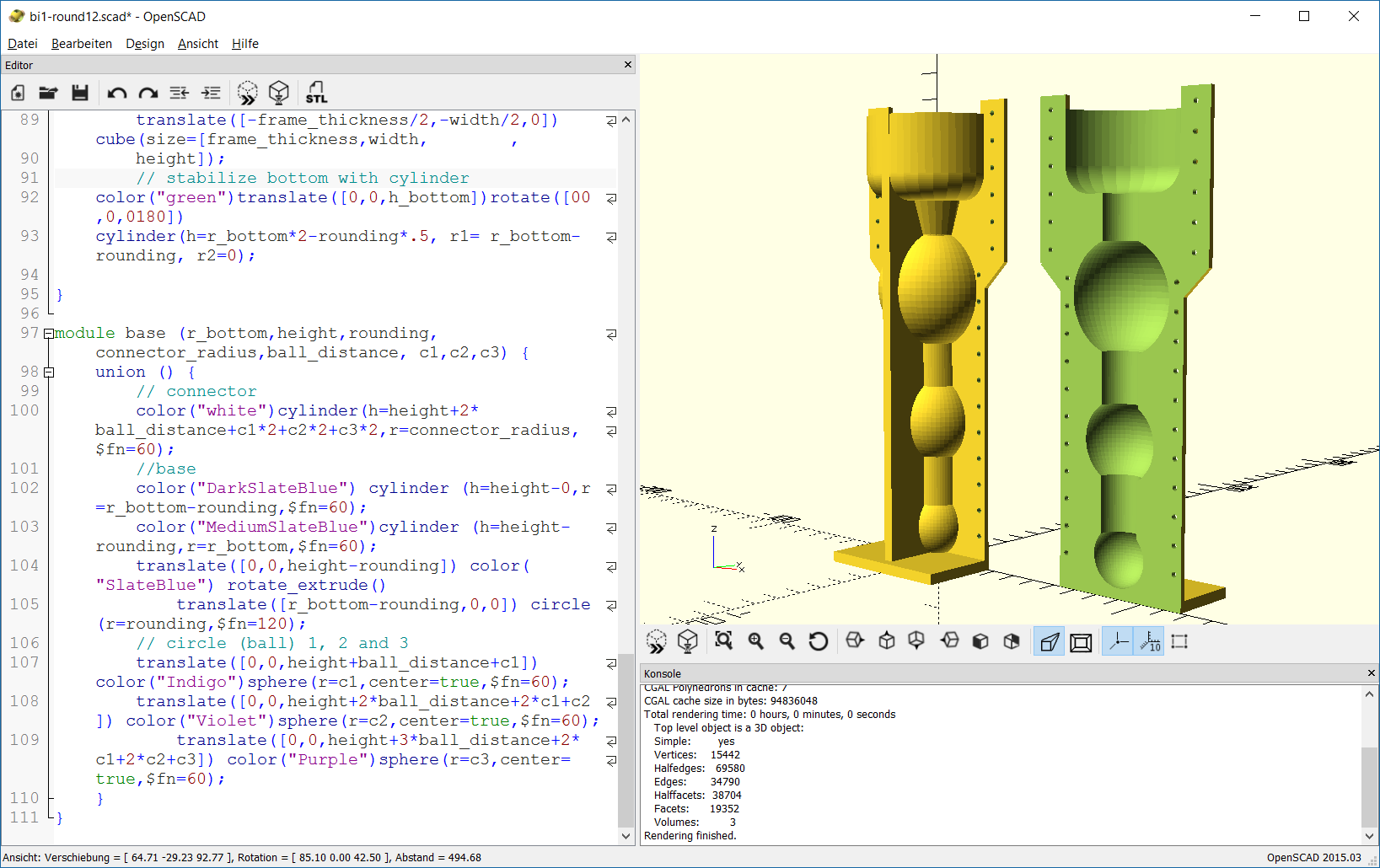 We have created a solution for molding form generation which is as flexible as our OpenSCAD sex toy generator. In addition you can change the thickness of the frame. Therefore you have to change the variable frame_thickness.
The SCAD script uses the module base which is already introduced. The generation of the frame is done in the module frame. The frame consists of a base plate and two supporting frames which stabilize the whole form. In addition there are extensions to the frame in the upper part of the form. These extensions will provide holes for fastening both forms.
The module complete_form constructs the form which is tricky. The union command is used to join the complete outer form and the frame. Now we have a filled form and have to remove the inner part. This is done by subtracting another complete form which is a bit smaller than the outer form. This is done with the difference command.
Another module hole provides all holes for the tinkering wire. At last we construct part A and part B of the molding form. Again the difference command is used to cut out one half of the form. This is done by subtracting a cube which is placed in the middle of the complete form. In addition the holes must be subtracted from the complete form.
 You can build in the body interaction vibrator development board to make a vibrating dildo, controlled by motion or by another body interaction vibrator development board. Read more here.
Try out with the Thingiverse customizer.
Download the zipped SCAD file here: bi1-round12
Or copy and paste the source code to the SCAD software:
// bodyinteraction toy form and mold form generator
// radius of bottom part
r_bottom=25; // [15:5:80]
// height of bottom part
h_bottom=30; // [10:5:80]
// top rounding of bottom part
rounding=10; // [10:5:20]
// radius of ball 1
r_ball1=21; // [15:5:50]
// radius of ball 2
r_ball2=15; // [15:5:50]
//radius of ball 3
r_ball3=11; // [15:5:50]
// radius of connecting cylinders
connector_radius=8; // [10:2:20]
// distance between balls and bottom part
ball_distance=15; // [10:2:40]
// offset (thickness of hull)
o=2;
// thickness of frame
frame_thickness=4;

height=h_bottom+3*ball_distance+r_ball1*2+r_ball2*2+r_ball3*2; echo(height);


// form part A
translate([0,0,height+frame_thickness])rotate([0,180,0])
difference() {
 complete_form(r_bottom,h_bottom,rounding,r_ball1,r_ball2,r_ball3,connector_radius,ball_distance,o,frame_thickness,height);
union(){
 translate([-r_bottom-o-10,0,-5])
 color("red")cube([2*r_bottom+2*o+20,r_bottom+2*o,height+frame_thickness+5]);
 holes(height,h_bottom);
 }
}
//form part B
translate([90,0,height+frame_thickness])rotate([0,180,0])
difference() {
 complete_form(r_bottom,h_bottom,rounding,r_ball1,r_ball2,r_ball3,connector_radius,ball_distance,o,frame_thickness,height);
union(){
 translate([-r_bottom-o-10,-r_bottom-o-2-10,-5])
 color("red")cube([2*r_bottom+2*o+20,r_bottom+2*o+10,height+frame_thickness+5]);
 holes(height,h_bottom);
 }
}

module holes (height,h_bottom){
for (i=[h_bottom+30:10:height])
 translate([r_bottom-1,5,i])rotate([90,90,0])
 color("green")cylinder(h=15,r=1,$fn=20);

for (i=[0:10:h_bottom+20])
 translate([r_bottom-3+10,5,i])rotate([90,90,0])
 color("blue")cylinder(h=15,r=1,$fn=20);

for (i=[h_bottom+30:10:height])
 translate([-r_bottom+1,5,i])rotate([90,90,0])
 color("green")cylinder(h=15,r=1,$fn=20);
for (i=[0:10:h_bottom+20])
 translate([-r_bottom-6,5,i])rotate([90,90,0])
 color("blue")cylinder(h=15,r=1,$fn=20);
}

module complete_form (r_bottom,h_bottom,rounding,r_ball1,r_ball2,r_ball3,connector_radius,ball_distance,o,frame_thickness,height) {
 difference() {
 union() {
 base(r_bottom+o,h_bottom+o,rounding,connector_radius+o,ball_distance-2*o,r_ball1+o,r_ball2+o,r_ball3+o);
 //complete frame
 frame(2*r_bottom+2*o,o,height,frame_thickness,r_bottom,h_bottom,rounding);
 };
 base(r_bottom,h_bottom,rounding,connector_radius,ball_distance,r_ball1,r_ball2,r_ball3);


};
}

module frame(width,o,height,frame_thickness,r_bottom,h_bottom,rounding) {
 //plate
 translate([-width/2,-width/2-2*o,height]) cube(size=[width,width+2*o,frame_thickness]);
 //frame1
 translate([-width/2,-frame_thickness/2,0]) cube(size=[width,frame_thickness,height]);
 //frame 1 extensions
 translate([-width/2-010,-frame_thickness/2,-5]) color("blue")cube(size=[12,frame_thickness,60]);
 translate([-width/2-10,-frame_thickness/2,55]) color("red")rotate([0,45,0]) cube(size=[12,frame_thickness,20]);

 translate([+width/2-2,-frame_thickness/2,-5]) color("green")cube(size=[12,frame_thickness,60]);
 translate([+width/2+01,-frame_thickness/2,47]) color("green")rotate([0,-45,0]) cube(size=[12,frame_thickness,20]);
 //frame2
 translate([-frame_thickness/2,-width/2,0]) cube(size=[frame_thickness,width, ,
 height]);
 // stabilize bottom with cylinder
 color("green")translate([0,0,h_bottom])rotate([00,0,0180])
 cylinder(h=r_bottom*2-rounding*.5, r1= r_bottom-rounding, r2=0);

}

module base (r_bottom,height,rounding,connector_radius,ball_distance, c1,c2,c3) {
 union () {
 // connector
 color("white")cylinder(h=height+2*ball_distance+c1*2+c2*2+c3*2,r=connector_radius,$fn=60);
 //base
 color("DarkSlateBlue") cylinder (h=height-0,r=r_bottom-rounding,$fn=60);
 color("MediumSlateBlue")cylinder (h=height-rounding,r=r_bottom,$fn=60);
 translate([0,0,height-rounding]) color("SlateBlue") rotate_extrude()
 translate([r_bottom-rounding,0,0]) circle(r=rounding,$fn=120);
 // circle (ball) 1, 2 and 3
 translate([0,0,height+ball_distance+c1]) color("Indigo")sphere(r=c1,center=true,$fn=60);
 translate([0,0,height+2*ball_distance+2*c1+c2]) color("Violet")sphere(r=c2,center=true,$fn=60);
 translate([0,0,height+3*ball_distance+2*c1+2*c2+c3]) color("Purple")sphere(r=c3,center=true,$fn=60);
 }
}
Go to the first part of the SCAD tutorial
OpenSCAD as sex toy generator
 OpenSCAD is a free software tool for creating 3d objects. But it is different from other CAD tools like Tinkercad or Freecad. Instead of using the mouse to select and modify 3d objects you have to use a description language. Making a 3d object in OpenSCAD is a bit like programming. For creating a sphere you just have to type sphere(r=10); where r is the radius of the sphere. For creating a cube or a cylinder just type in the appropriate command. When done select compile from the menu and you’re object will be displayed.
Just download the OpenSCAD software, install the tool and try out a command. You can copy and paste the dildo generator source code (at the end of this blog post) and try to change the parameters. Another option is to use the customizer module of the Thingiverse platform.
Brief Intro to OpenSCAD
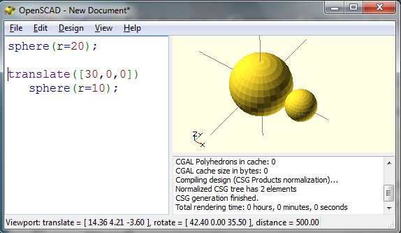 If you want to create a sphere not in the origin but somewhere else you have to shift the object using the translate command. For creating the second smaller sphere use
translate([30,0,0]) sphere(r=10);
The translate command moves the sphere objects on the x-axis by 30 points.
To visualize the form use the design menu and select “compile” or “compile and render”. Rendering takes some time (up to some minutes) but it will give you a correct preview of your form.
To build more complex objects you have to use the union or difference command. The union command puts simple objects together. With the difference command you can cut out something e.g. to make a ring. 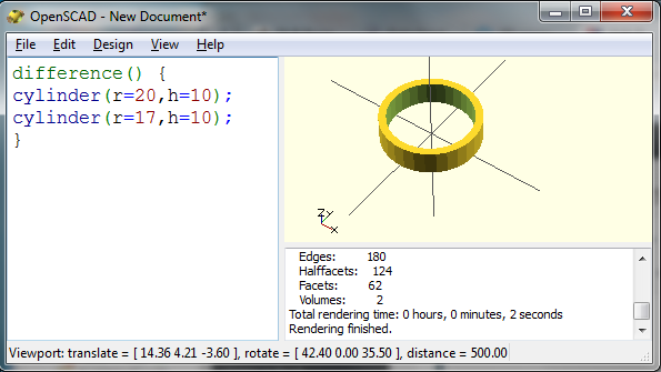 You can download a STL-file (select “export STL” from the menu) and print out the form with a 3d printer.
OpenScad can be used to create sex toys as shown by Mr O. He used OpenScad to create basic building blocks for sex toys which can be combined and changed in size. Moreover with OpenScad you can make generative designs. For example you can make a generative dildo which can be individualized by changing parameters like height, length etc.
Generative Dildo Project
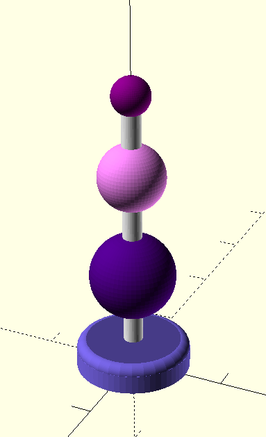
Let us create the “balls” dildo which is introduced in Silicone overmolded vibrator – balls revisited and Update for “balls revisted” – silicone molded vibrator.
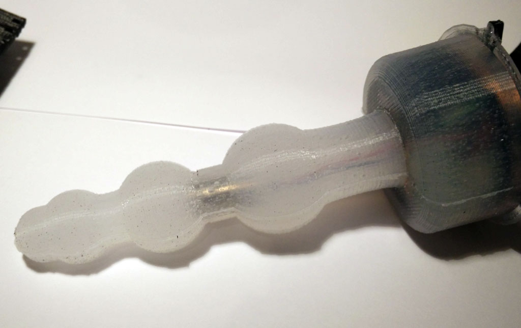 The dildo consists of 6 forms:
- three spheres with individual radius
- a base which is made of cylinders
- and an iterative use of circles to make the upper top of the base to be round
We use the module command to encapsulate the commands for creating the dildo. A module is very similar to functions or procedures in other programming languages, but they do not return a value. They just execute the commands in the module. The definition of the module starts with its parameters.
module base (r_bottom,height,rounding,connector_radius,ball_distance, c1,c2,c3) {
  ...commands for creating the dildo...
}
c1, c2 and c3 are the radius of the spheres. r_bottom is the radius of the base part and height the height if the base parts.
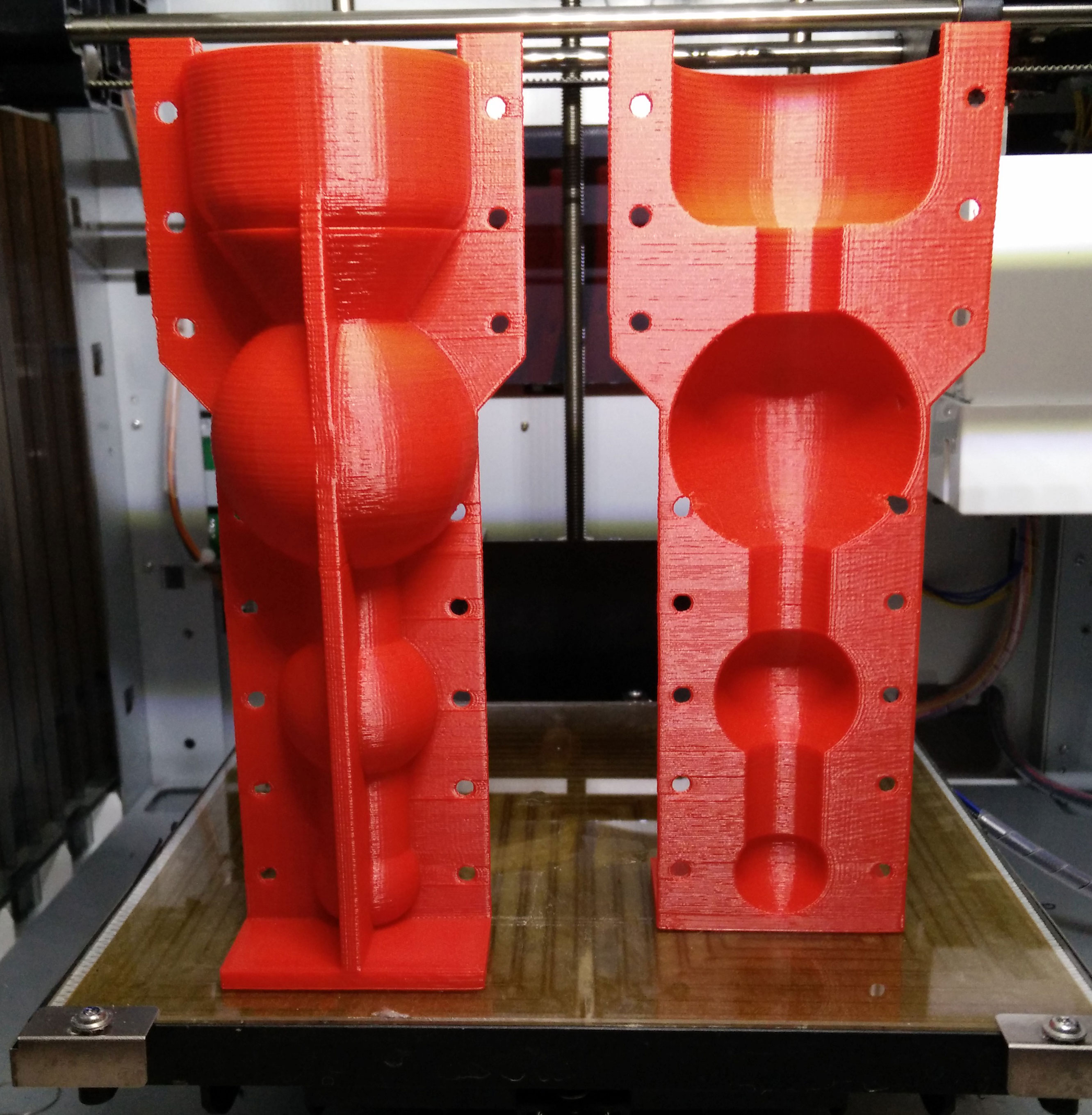
Now you can produce different versions of the ball motive by entering different parameters when you call the module base. With the following parameters the form at the left side will be generated:
base(50,60,10,10,30,15,25,35);
 This form will be made when using the following parameters:
base(60,30,10,10,30,20,35,45);
Make your own generative sex toy design and publish it
The Thingiverse platform is able to create objects made with OpenSCAD. Just upload the SCAD-file to Thingiverse using the customizer option. Now you can change the parameters within Thingiverse and generate a customized STL-file for 3d printing. Try it out with the Thingiverse customizer (as long as nobody complains…).
Download the SCAD file source code here: form_only
Or copy & paste the following SCAD code to generate the “balls” sex toy:
// bodyinteraction toy form

// radius of bottom part
r_bottom=50; // [50:5:80]
// height of bottom part
h_bottom=60; // [10:5:80]
// top rounding of bottom part
rounding=10; // [10:5:20]
// radius of ball 1
r_ball1=35; // [15:5:50]
// radius of ball 2
r_ball2=25; // [15:5:50]
//radius of ball 3
r_ball3=20; // [15:5:50]
// radius of connecting cylinders
connector_radius=10; // [10:2:20]
// distance between balls and bottom part
ball_distance=30; // [10:2:40]


base(r_bottom,h_bottom,rounding,connector_radius,ball_distance,r_ball1,r_ball2,r_ball3);

module base (r_bottom,height,rounding,connector_radius,ball_distance, c1,c2,c3) {
 union () {
 // connector
 color("white")cylinder(h=height+2*ball_distance+c1*2+c2*2+c3*2,r=connector_radius,$fn=60);
 //base
 color("DarkSlateBlue") cylinder (h=height-0,r=r_bottom-rounding,$fn=60);
 color("MediumSlateBlue")cylinder (h=height-rounding,r=r_bottom,$fn=60);
 translate([0,0,height-rounding]) color("SlateBlue") rotate_extrude()
 translate([r_bottom-rounding,0,0]) circle(r=rounding,$fn=120);
 // circle (ball) 1, 2 and 3
 translate([0,0,height+ball_distance+c1]) color("Indigo")sphere(r=c1,center=true,$fn=60);
 translate([0,0,height+2*ball_distance+2*c1+c2]) color("Violet")sphere(r=c2,center=true,$fn=60);
 translate([0,0,height+3*ball_distance+2*c1+2*c2+c3]) color("Purple")sphere(r=c3,center=true,$fn=60);
 }
}
Moving dildo with motor driven skeleton
 So far we have used vibration motors for our sex toys. Vibration motors are cheap, powerful, easy to control and robust actuators. That’s why they are part of most sex toys. But what about moving or touching objects. Obviously we need some mechanics, maybe joints and gears? Or is there a simple option? A skeleton?
I realized the idea for using some type of skeleton for moving a dildo when I saw the video of a naked Pleo – one of the best artificial life forms ever.

On www.thingiverse.com you will find more inspiration for using a skeleton to move something. The design is very simple.
The skeleton is composed of a number of vortexes. The holes are for connecting all vortexes and a servo with a nylon wire or similar.
In addition we need a handle where the vortexes are fastened to. There is also space for a servo. Then use a nylon wire to connect the vortexes with the servo. You can drive the servo with a Arduino development board or you use the body interaction development board as described here.

The servo should turn only 15-30 degree or so. If you use the body interaction development board please copy the following code and upload the code to the board.
#include <TinyServo.h>
// servo control with the body interaction development board using the TinyServo library
// -- adaption of the demo script by
// tylernt@gmail.com's ATTiny Hardware Timer Assisted Servo Library v1.0 20-Nov-13
// http://forum.arduino.cc/index.php?action=dlattach;topic=198337.0;attach=71790
const byte SERVOS = 1; // number of servos is 1
const byte servoPin[SERVOS] = { 7 }; // servo is connected to PA1 which is pin 7
#define SERVO 0 // our servo is given the name &quot;SERVO&quot;
void setup() {
setupServos();
}
void loop() {
moveServo(SERVO, 0); // move servo to 0°
delay(1000);
moveServo(SERVO, 30); // move servo to 30°
delay(2000);
}
In addition we need a wrapping for the skeleton. This can be made using these two forms (download STL files).
Use flexible silicone and poor it in the form. The thickness of the wrapping is a bit too large – it rather hinders the skeleton in its movements. But it works!

Now we can put everything together.
Download on Thingiverse: http://www.thingiverse.com/thing:1736282
Tinker with Tinkercad!
Form: https://tinkercad.com/things/e8yscABu9Al
Skeleton: https://tinkercad.com/things/dfbMQsE4Mtl
Servo handle: https://tinkercad.com/things/5EHHrqM5sqC
YouTube: https://youtu.be/F1b8bGbuSHw
New small fusion vibrator
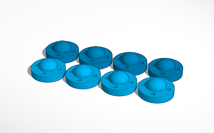
 This is a small version of the fusion vibrator. The small fusion form for molding can be made with 3d printers with smaller volume. In addition the inlay for the body interaction development board is reduced in size, but there is still enough place for board and battery. Only about 120ml silicone are needed. The form was constructed in Tinkercad.
Modify the form in Tinkercad: all forms, inlay only, form only
Download the STL files for printing: round_something_06_final_inlay_improved. There are some artifacts but printing is fine on the daVinci 1.0.
Download and discuss in Thingiverse: http://www.thingiverse.com/thing:1589075

Please follow the instruction from the large fusion vibrator. When you poor the silicone into the form it is very important to keep the USB connector free from silicone. Even very small amounts can cause the USB connector to break apart from the board. When the USB connector is broken then you cannot recharge the vibrator. Also be always very cautious when you plug-in or plug-out the USB connector.


Finally you can remove the overhanging parts from the inlay.


USB powered charging station for the silicone molded vibrator
 We made a DIY silicone molded vibrator (see here, here and here) using the Arduino compatible body interaction vibrator development board and a wireless charging module. Now we need a charging station where you can put your vibrator for battery charging.
We need a simple box for the wireless charging sender (transmitter) module and the coil. In addition we need a USB cable which we will cut though and connect to the charging module.
It is important to keep the distance between sender and receiver coil as small as possible. The larger the distance is the less power will be transmitted. Therefore the plate where you put the vibrator must be very thin. There are different modules available.
What do you need?
- A USB cable
- Wireless charging sender (transmitter) eg. from Seeed Studio, 5V input. The sender (transmitter) will be placed in the charging station. The receiver module will be part of the vibrator. There are different modules available. Look for a 5V input module.

Instructions:
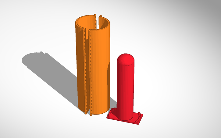
A. Print out part A and B. Download STL files (zip file)

B. Cut a USB cable. Plug the cable through the hole of form B.
C. Now connect the USB wires with the sender module. Solder the red wire to the (+) pad on the wireless charging sender. Solder the black wire to the (-) pad.

D. Glue the sender board on the bottom of the red form. Put some glue on the cable to fix it. We used hot glue.

E. Now glue the black form and the sender coil together. We used simple “UHU”-like glue. If the distance between coil and form is too large the charging could be rather slow. So don’t use too much glue.
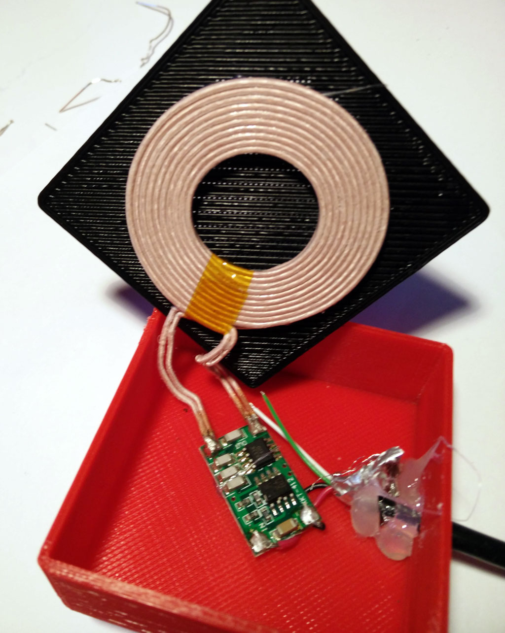
F. Now put together both parts. Again we used a simple glue.
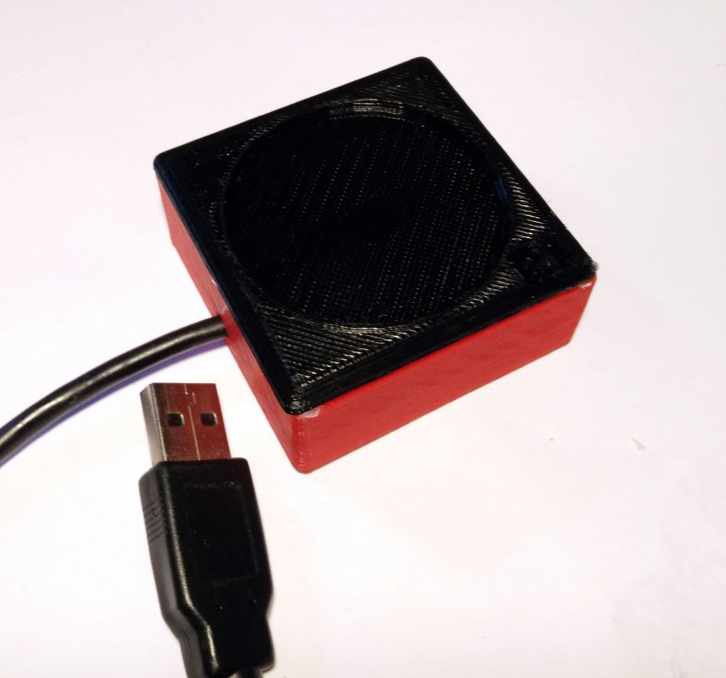
G. Insert the USB connector to your PC or any other source. Now the vibrator should be charged which is indicated by an orange LED.
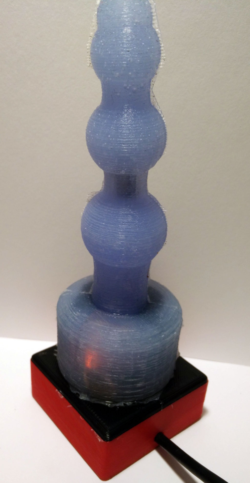 Ready! Have fun with your collection of wireless DIY Arduino-compatible vibrators.
Download STL files (zip file)
All files at Thingiverse: http://www.thingiverse.com/thing:1488428
Tinker and share with Tinkercad:
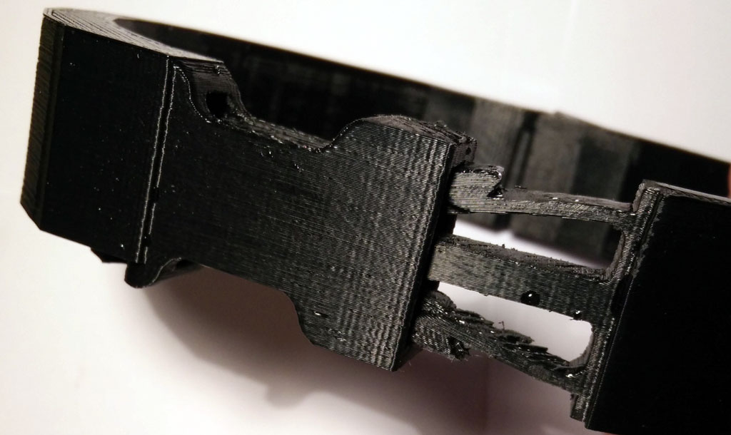
Vibrating 3d Printed Necklace
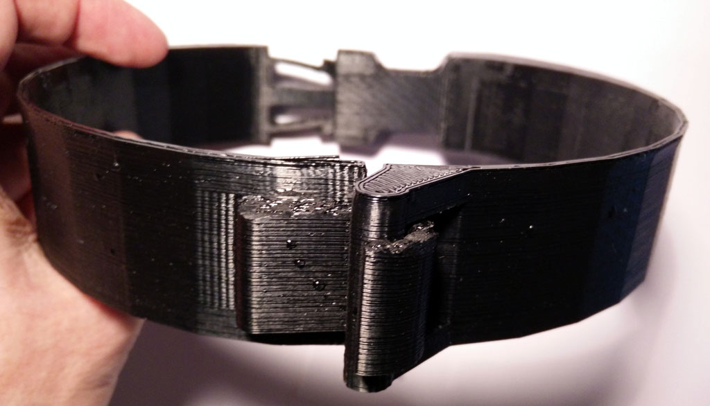 There are a lot of sensible areas of the body which are also erogenous zones (see Wikipedia). The neck is one of them. Stimulation can be achieved eg. by licking and kissing. The stimulation can be quite strong. So why not try to stimulate your neck with vibration? We think it works.
Think of an artistic designed necklace or collar with a vibration function. The vibration will be turned on when you move and gets more intense when you shake our head eg. while dancing. Or the vibration function will be turned on remotely by your friend.
 Body interaction has made a 3d design for a vibrating necklace. It can be secured by a solid clip closure at the back of the neck. At this place the vibration motor is positioned which gives an intense vibration especially at the back of the neck but also at the whole neck.
 The body interaction vibrator development board is inserted into the collar. It controls the vibration motor. The more you move the more it vibrates. There is also place for the battery. Wires and boards can be hidden. Unhidden it has a scifi look-alike.
 In the front there is a solid but easy to close hook closure.
Download 3d files from Thingiverse and print it.
Get the vibrating electronics from Tindie.
Edit and design your own with Tinkercad https://tinkercad.com/things/8stCwczMAkp

Wireless battery charging of the body interaction vibrator development board

 One major Problem oft DIY electronic sex toys (or massage wands) are the need to charge the batteries. Usually the batteries are charged via the USB connector. This means that there is a physical connection between the sex toy and the USB connector, making it impossible to mold the whole sex toy with eg. silicone.
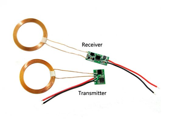
The solution is to use a wireless charging module (eg. this module from Seeedstudio). It comes in two parts: The sender (IN) and the receiver (OUT). Both are connected with a coil. If you place the two coils close together, the sender coils induces power in the receiver coil. Though you can share the batteries wireless. The receiver could be molded, separating the electronics, batteries, connectors etc. from the environment. The result is a form with a smooth surface enabling secure usage as a sex toy.
 We have made an easy DIY solution based on the body interaction vibrator development board, wireless charging module and a 3d printed silicone molding form.

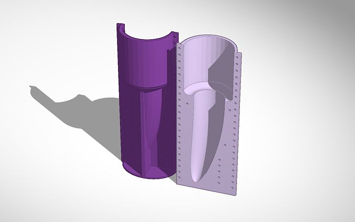
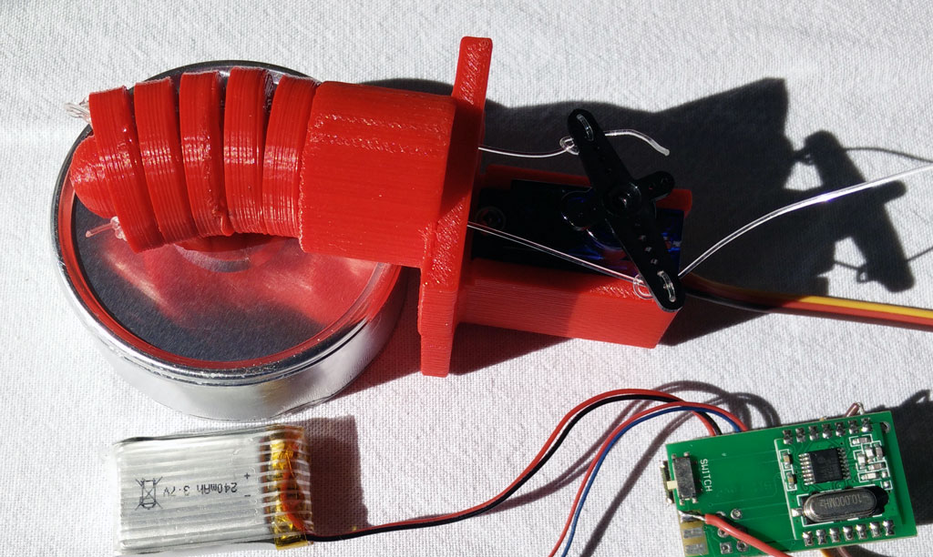
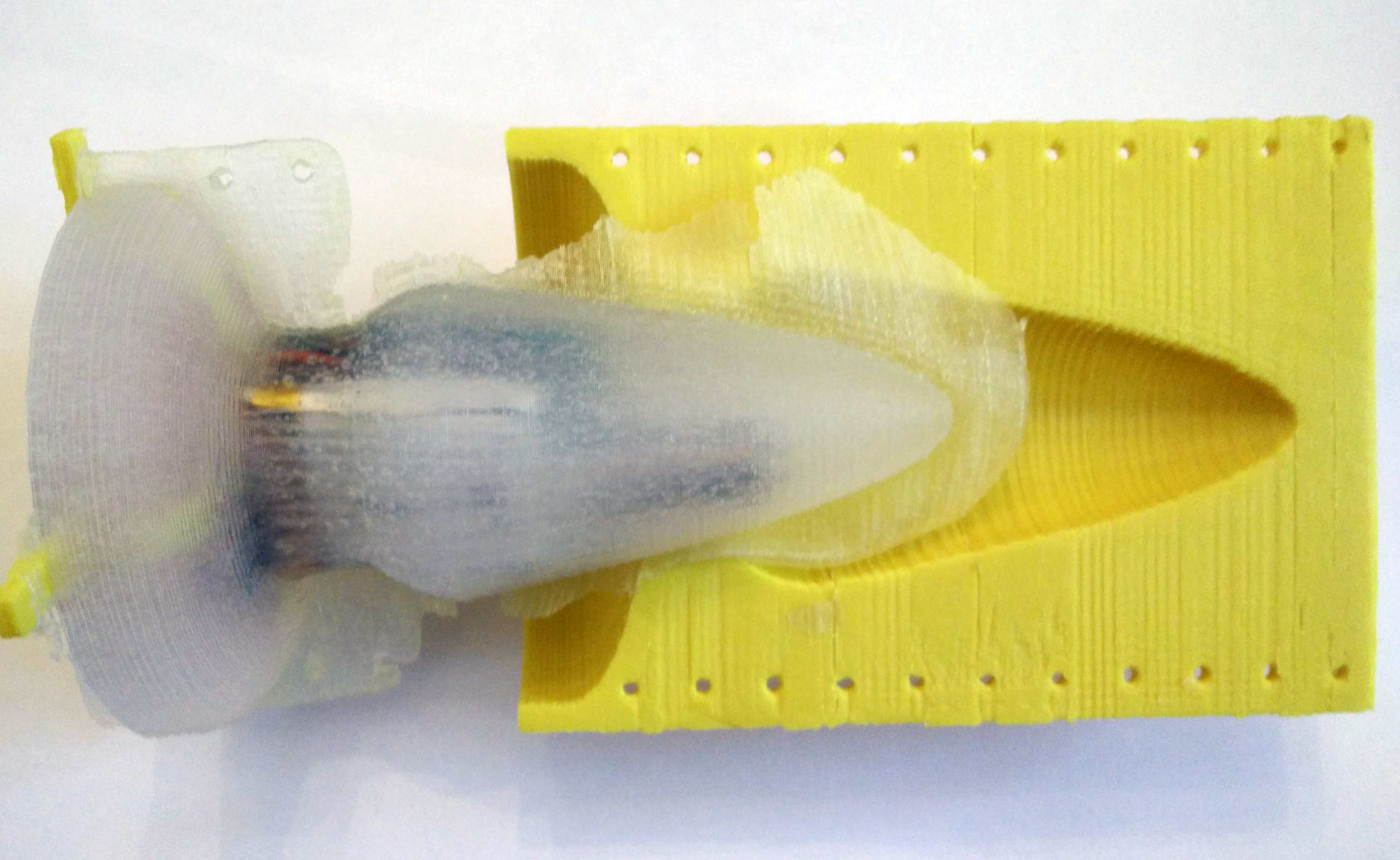
Part A: The molding form consists of two parts.

3d print form A
Step 1: The form comes in 2 parts. Print both parts of the form. The STL file is called part A. After printing polish the inner part of the form as well as the surface between the two sides.
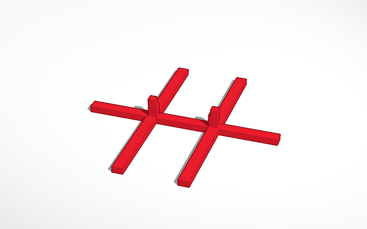
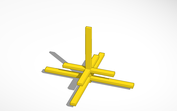 Step 2: Now print out part B. It is used to fasten the board, battery, receiver coil and receiver board.
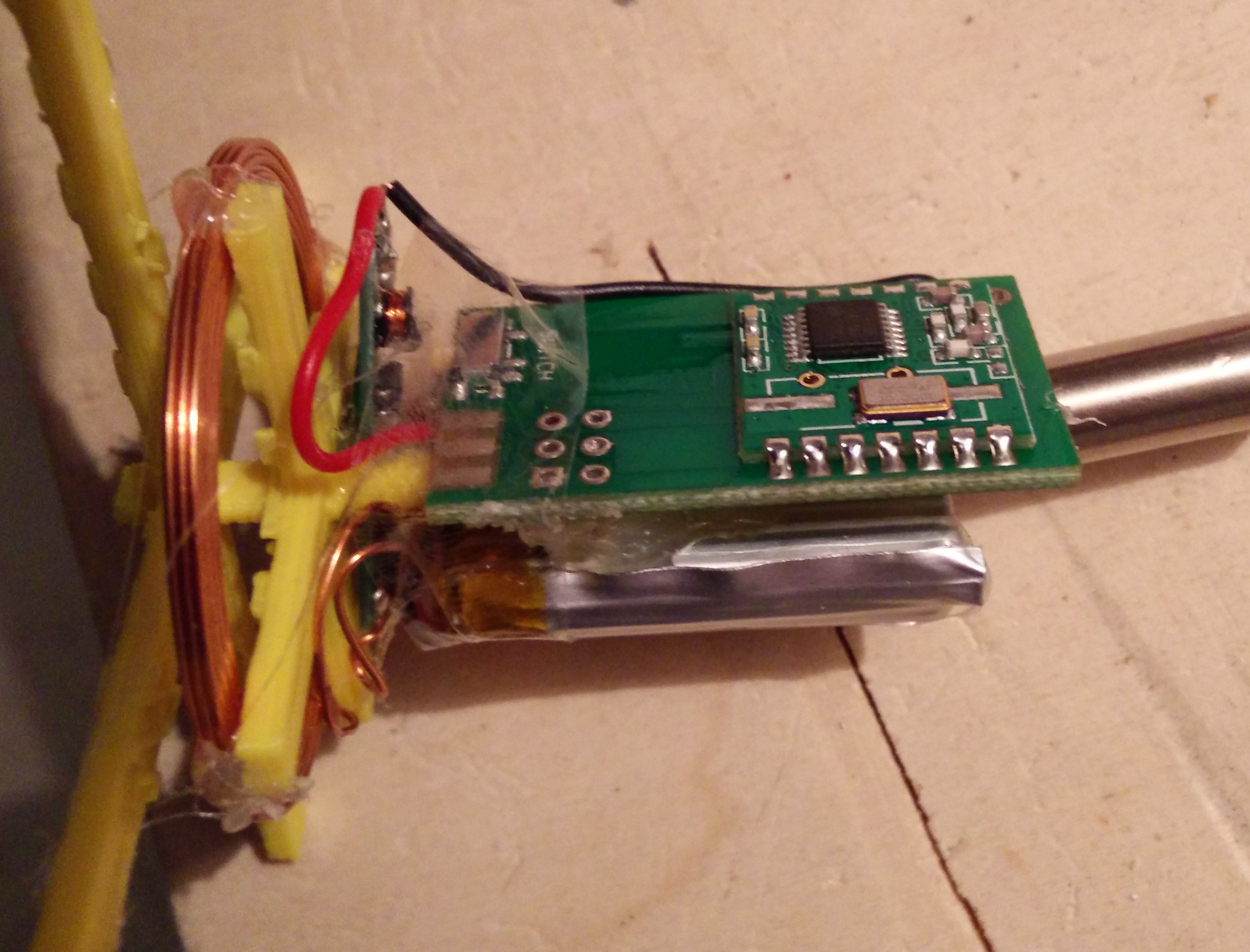
 Step 3: Connect the + pad of the wireless charging receiver board with the pin marked + of the vibrator development board (that’s pin 1 of the MAX1555 battery charging IC). Connect – of the receiver with the GND pad of the vibrator development board. You need two short wires and have to solder them at the two boards.
 Step 4: Now wind up the wires connecting the board with the battery and the vibration motor. (The connection to the receiver board is not shown on the image.)

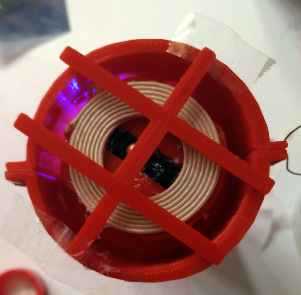
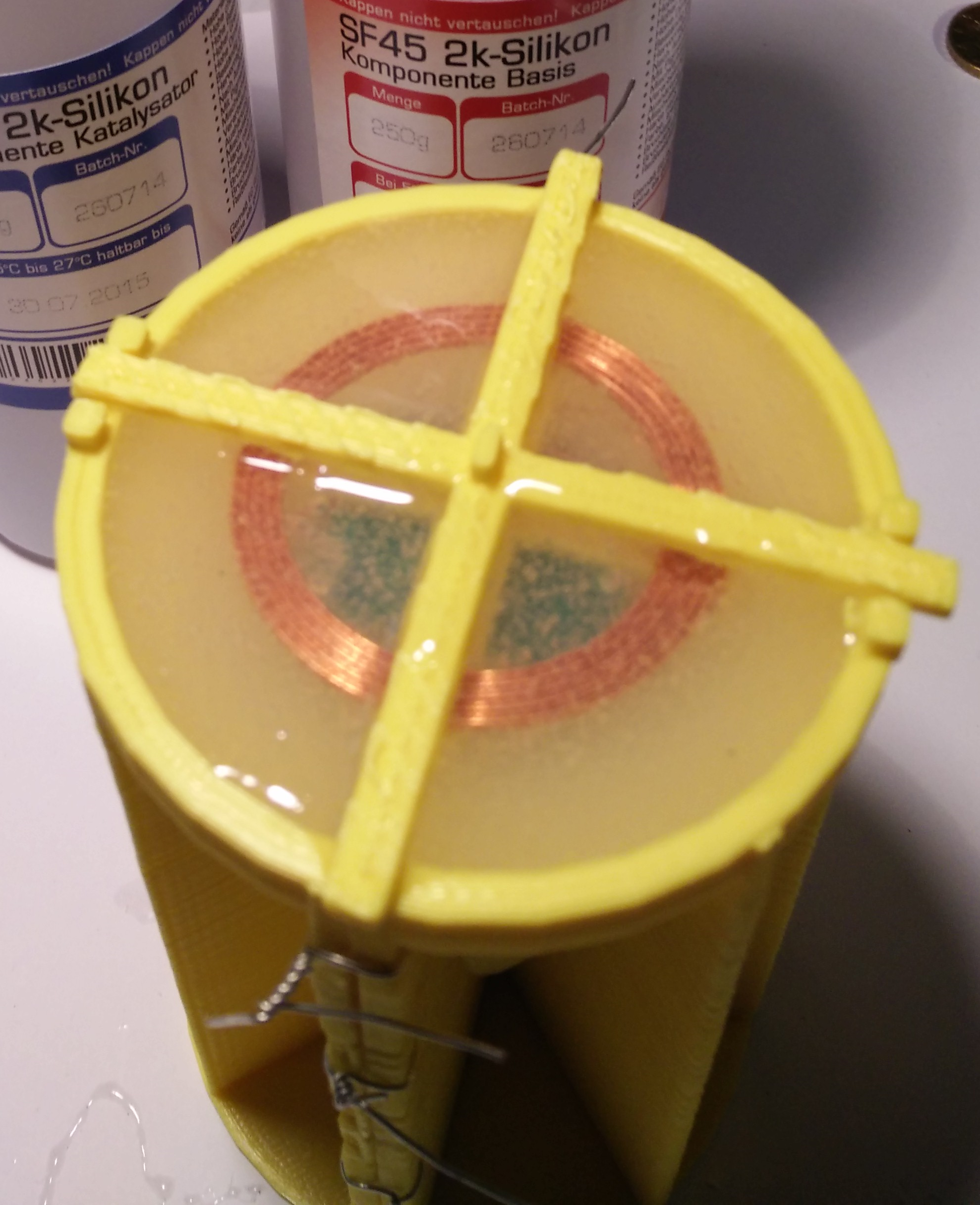
 Step 5: Now attach the coil on the shorter “cross” of part B with some glue. There must be space between the coil and the outer longer cross. Then attach the board, battery and vibration motor as shown in the pictures. you can use some glue to fix these parts. Be sure to set the switch to the ON position.
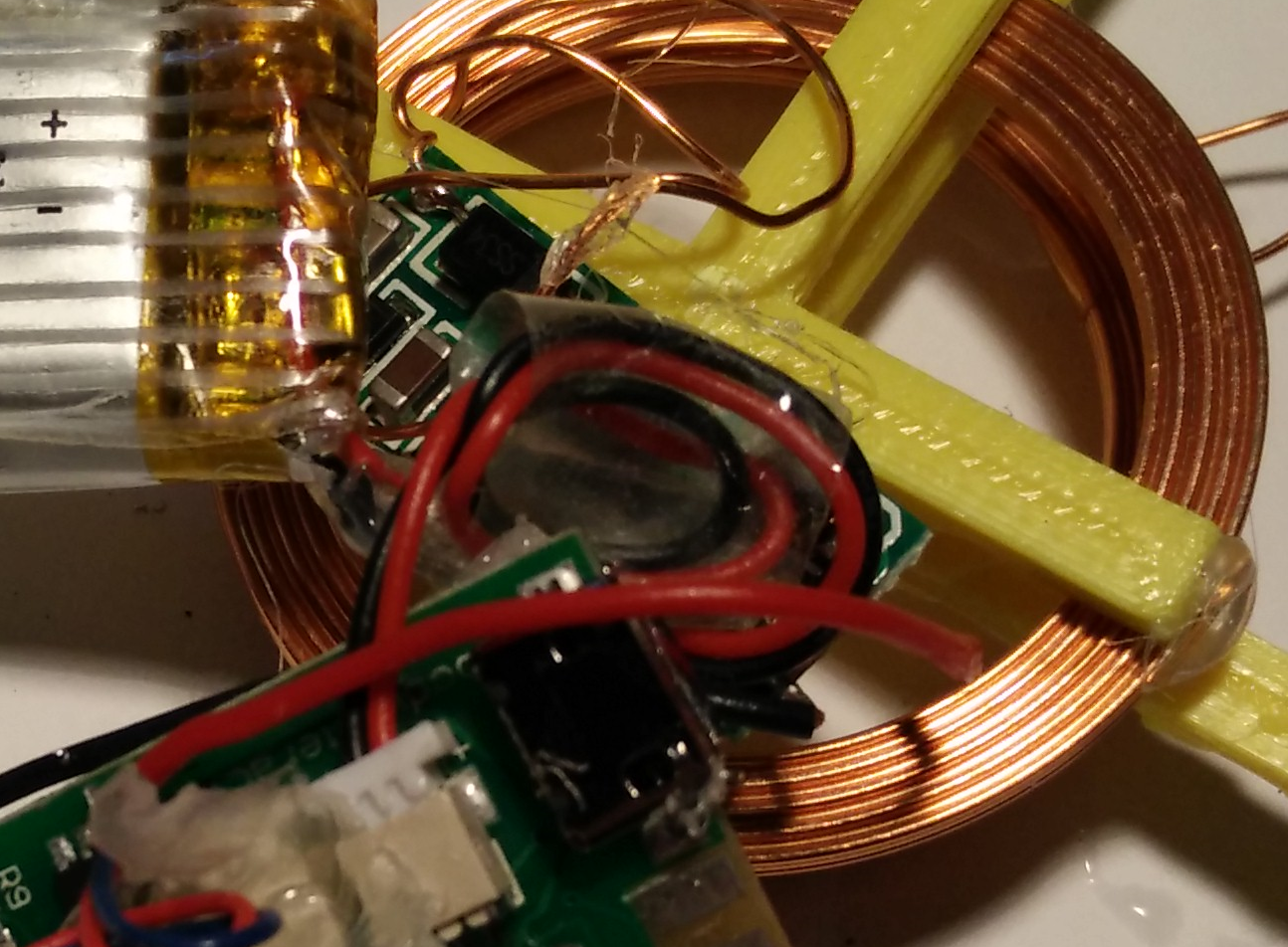 The receiver board can be placed within the coil. It’s the small long board in the middle.
 Step 6: Fix part B (with board, coil etc.) at part A. Be sure that there is enough space between them (min. 5mm).
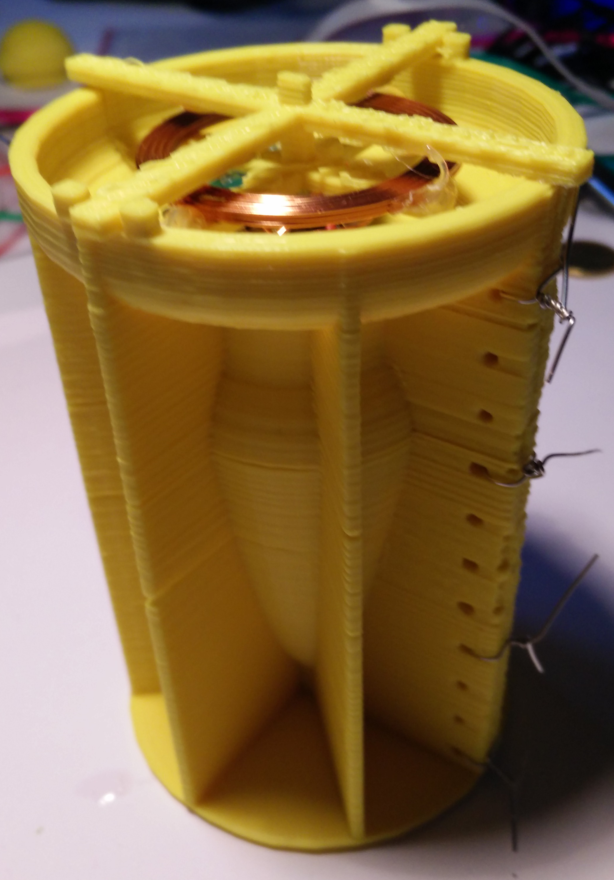

 Step 7: Now attach the second part of part A. Use some tinkering wire. Double check: There must be space between Part A and part B. And there must be space between the coil and the upper edge of form A as the coil must be molded by the silicone.
 Step 8: Now pour silicone into the form. Use silicone with a high Shore A value. The higher the Shore A value is the higher is the firmness of the silicone form. We have used silicone with Shore A 45. You need about 90 ml silicone.
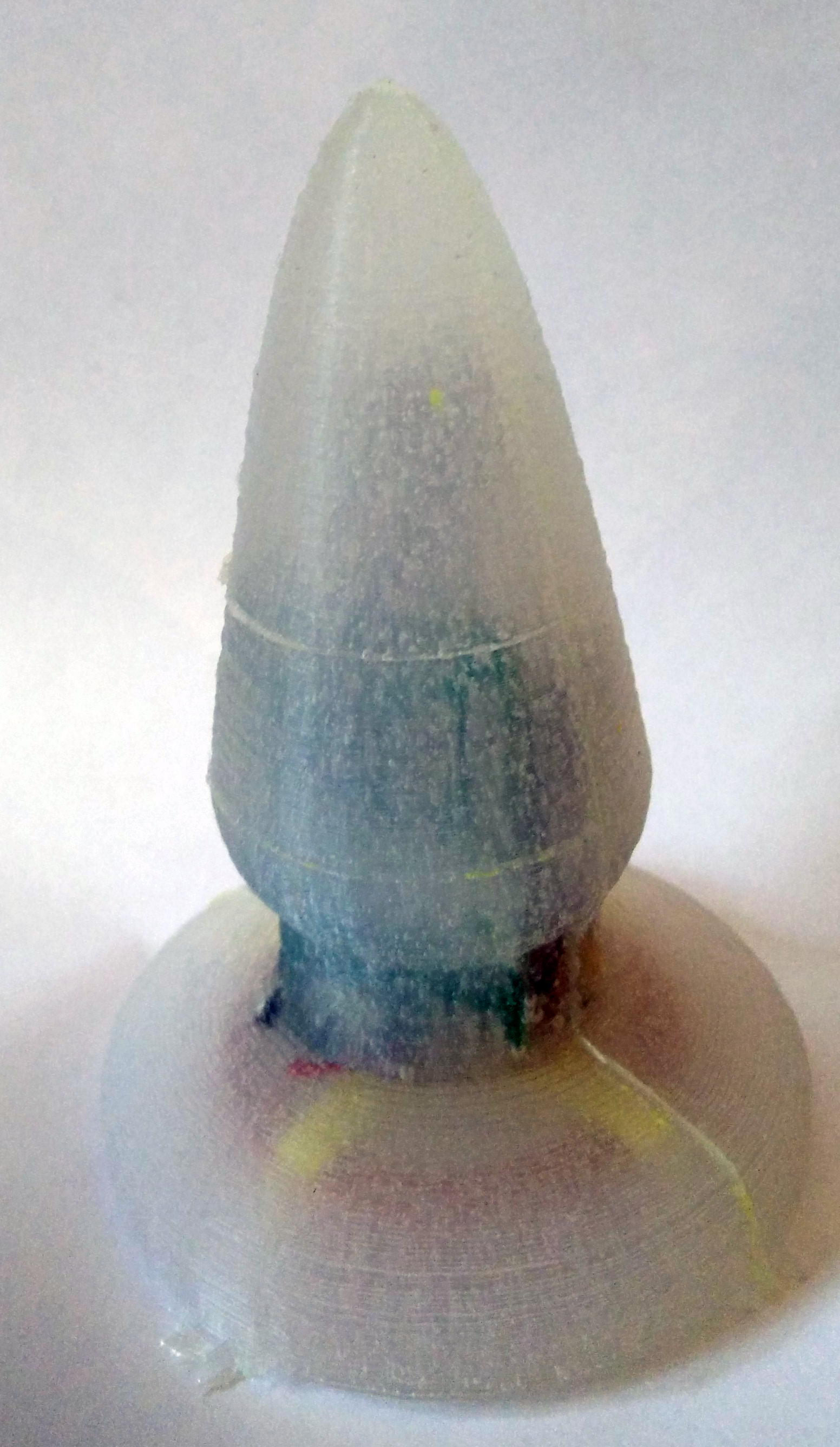
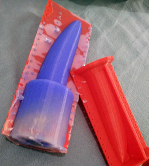
 Step 9: After the silicone gets hard, remove the tinkering wires and softly remove the form A. Remove overhanging part.
Step 10: Now you can remove the outer cross of part B.
 That’s it. It takes about half an hour (without printing). Before using check carefully that the silicone is solid. Even if you skew the silicone form you should not be able to feel the edges of the vibrator development board. Otherwise there is the danger to get hurt. Use it as a massage toy on your own risk. For charging the batteries place the molded coil over the sender coil. The yellow charging LED should go on.
The next development step is a battery charging station!
Download 3d printing files from Thingiverse
Modify and construct your own with the online 3d modelling software Tinkercad: Form A, Form B
