As alternative to the 3d printed form a flexible form made with silicone could improve the handling of the body interaction board (BI1) for certain applications. The vibration is more comfortable and less noisy compared to other cases. If you want to do it on your own follow this how-to.

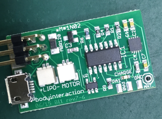
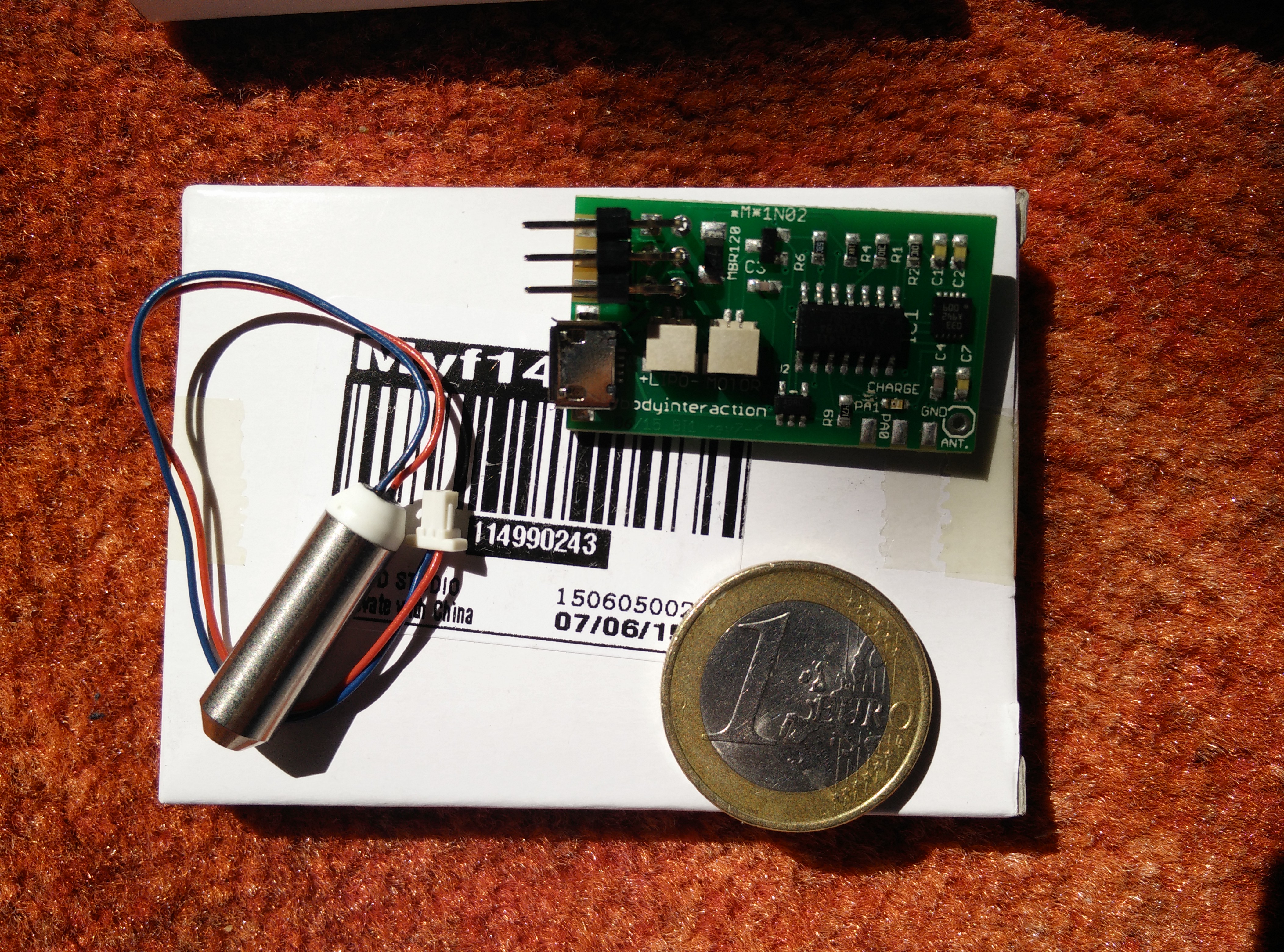
Silicone molded BI1: vibration motor (top), RF12b (bottom)
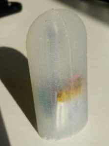
silicone molded BI1 board – vibration motor (top), LiPo (bottom)
Some adult toys are made of silicone or at least are coated with silicone. Silicone cases are easy to clean.
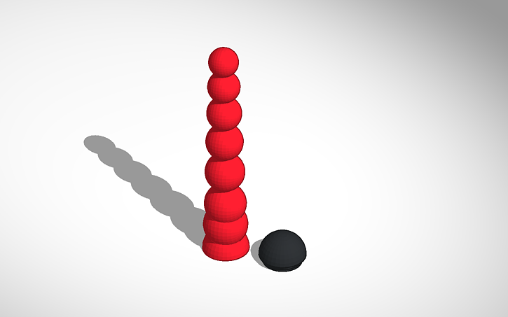
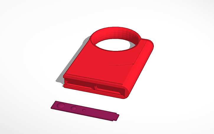
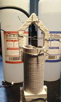
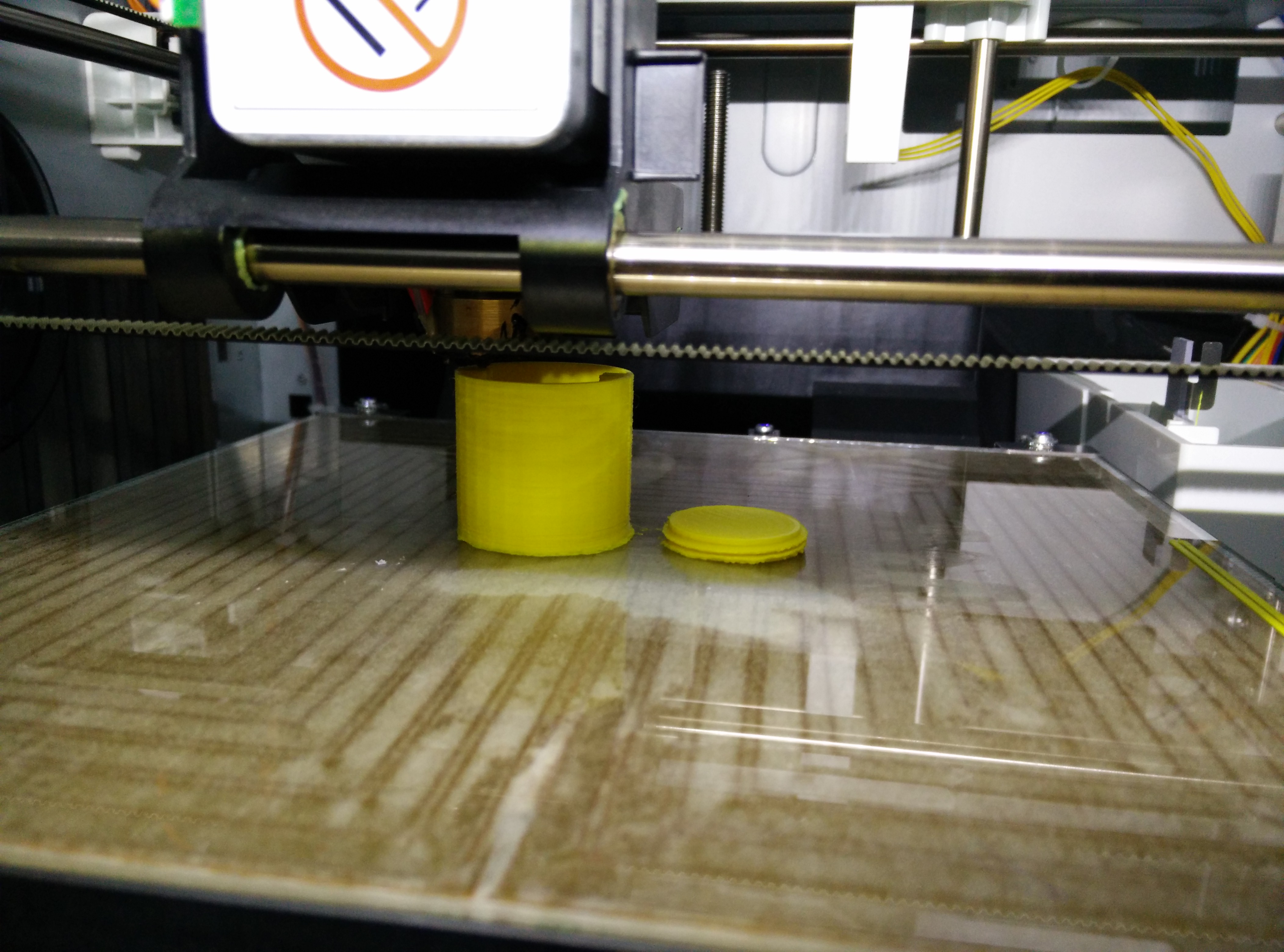
We have constructed a 3D printed form where we will fill in the silicone. The form comes in two parts that have to be fixed to one another by tinkering wire. In addition the board has to be hooked to the form. For this we use a USB connector which is plugged in the USB port of the board. Then the USB connector is fastened to the form.

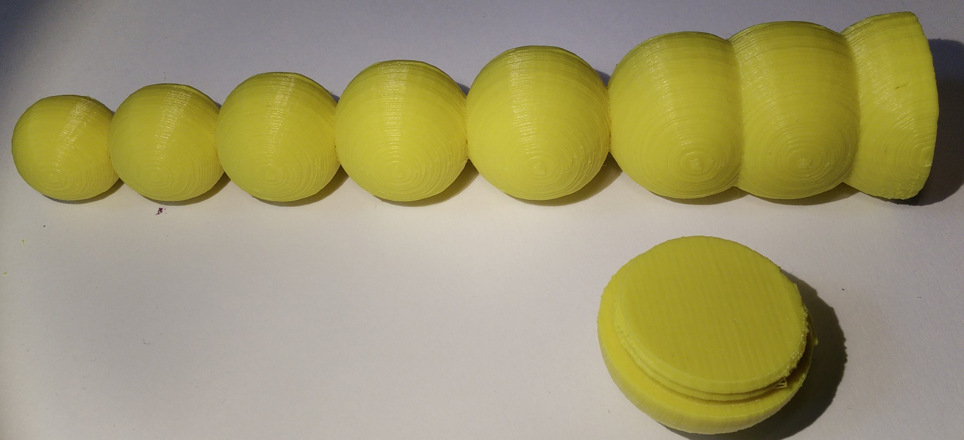
Form for molding

USB connector holding BI1 board is fastened with tinkering wire
Use a silicone which will become solid after moulding. This property of silicone is indicated by the shore A value. Silcone with a low value is flexible. We use silicone with shore A 43.

Molding form with USB connector and 2 component silicone shore a 43
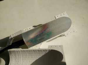
molded BI1 and 3d printed form
Do you want to try it on your own? Follow this how-to and tell us your experience.

 Instead of printing a vibrator case we construct a form for overmolding the body interaction vibrator development board. The updated overmolding process is described here
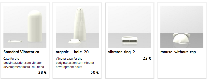
![IMG_20150901_211915[2]](https://bodyinteraction.com/wp-content/uploads/2015/09/img_20150901_2120102.jpg)
![IMG_20150901_212010[2]](https://bodyinteraction.com/wp-content/uploads/2015/09/img_20150901_2120102.jpg?w=169&h=300) All you need for assembly is the body interaction motion controlled vibrator development board and two M3 screws (about 6mm long).
All you need for assembly is the body interaction motion controlled vibrator development board and two M3 screws (about 6mm long).