Controlling the vibration motor
The vibration motor is an analog device. You can control the vibration on a scale between 0 and 255. If you set the vibration to 0 the motor is off, if you set the vibration to 255 the motor will be at full speed.

Good vibrations Tokyo by Kevin Dooley, CC BY 2.0
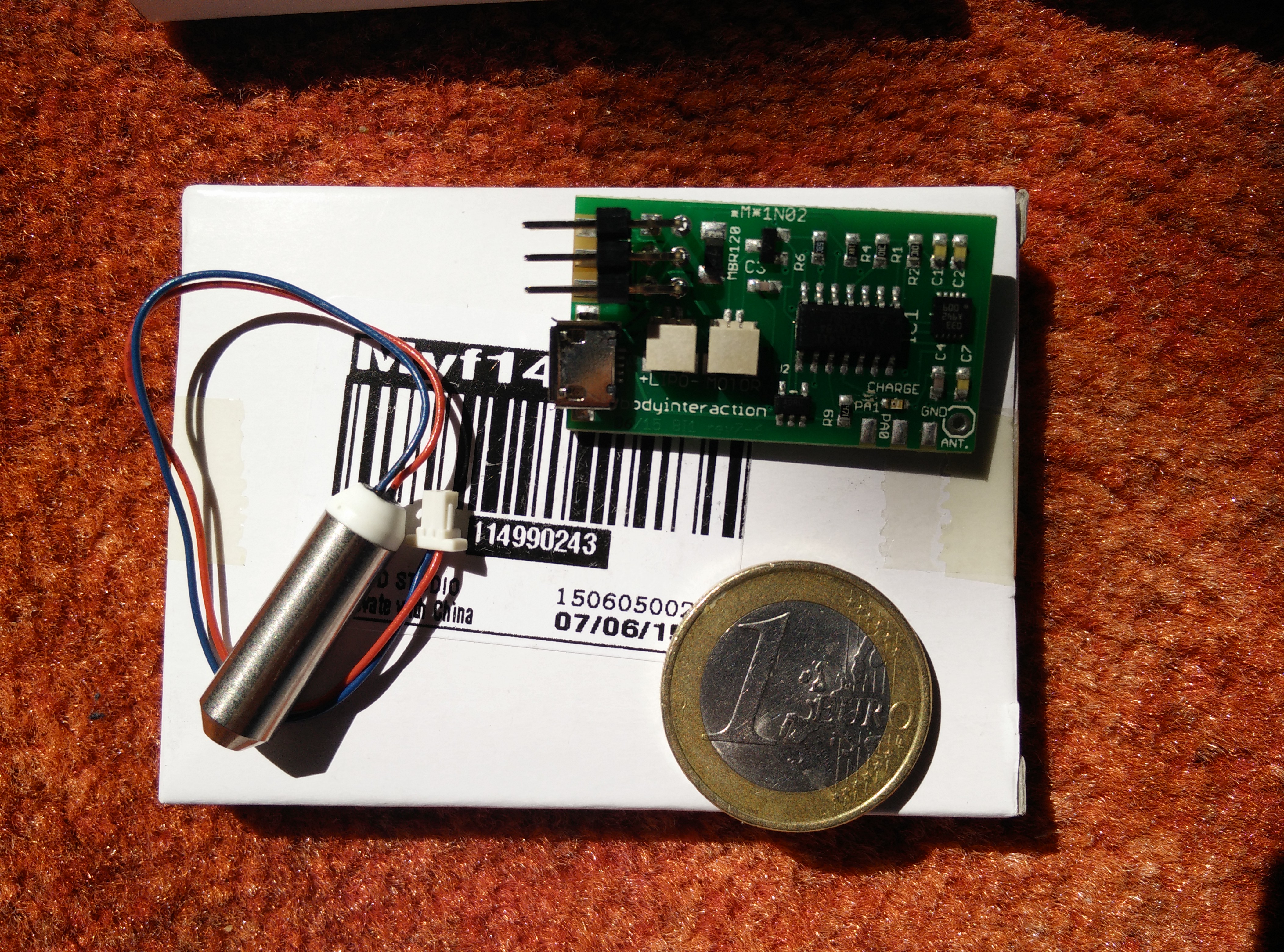
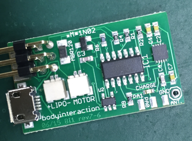
The motor is connected to a pin of the controller (“ATtiny84”), the heart of the BI. Every pin has a number and the motor is always connected to pin 3.
 Now we can start with the first script (or program). The script will set the motor to full speed for one second. Then the motor will be off for 1 second. And this will be repeated infinite.
Here is the complete script:
int motor=3;
void setup() {
  pinMode(motor, OUTPUT);
}

void loop() {
  analogWrite(motor, 255); //motor on
  delay(1000);  // wait for 1 second
  analogWrite(motor, 0); //motor off
  delay(1000);
}
Now the script is explained line by line:
int motor=3;
First we declare a variable called “motor” and assign the value 3. The variable is of type int (integer) which is used to store a number. Now we could use “motor” instead of “3” whenever we want to control the vibration motor – this will help us to understand and debug our script.
void setup() {
  …
}
This is function which is part of every Arduino script. It is called setup and well be executed at first and only once.
pinMode(motor, OUTPUT);
Each pin can be in INPUT or OUTPUT mode. In input mode sensor data can read, in output mode a motor or a LED can be controlled. We set the motor pin to OUTPUT.
void loop() {
  …
}
In the function loop we put all the instructions which should be carried out. When all instructions are done the script doesn’t stop but starts again. Therefore the loop will be repeated infinite.
analogWrite(motor, 255);
The motor is set to full speed (255).
delay(1000);
The delay function stops all processing for 1000 milliseconds. 1000 millisecond are 1 second.
analogWrite(motor, 0);
Then motor is set off (0). In the second part of the tutorial uploading of the script to the body interaction 1 is explained.
More:
https://www.arduino.cc/en/Tutorial/Foundations
Read part 2: the accelerometer


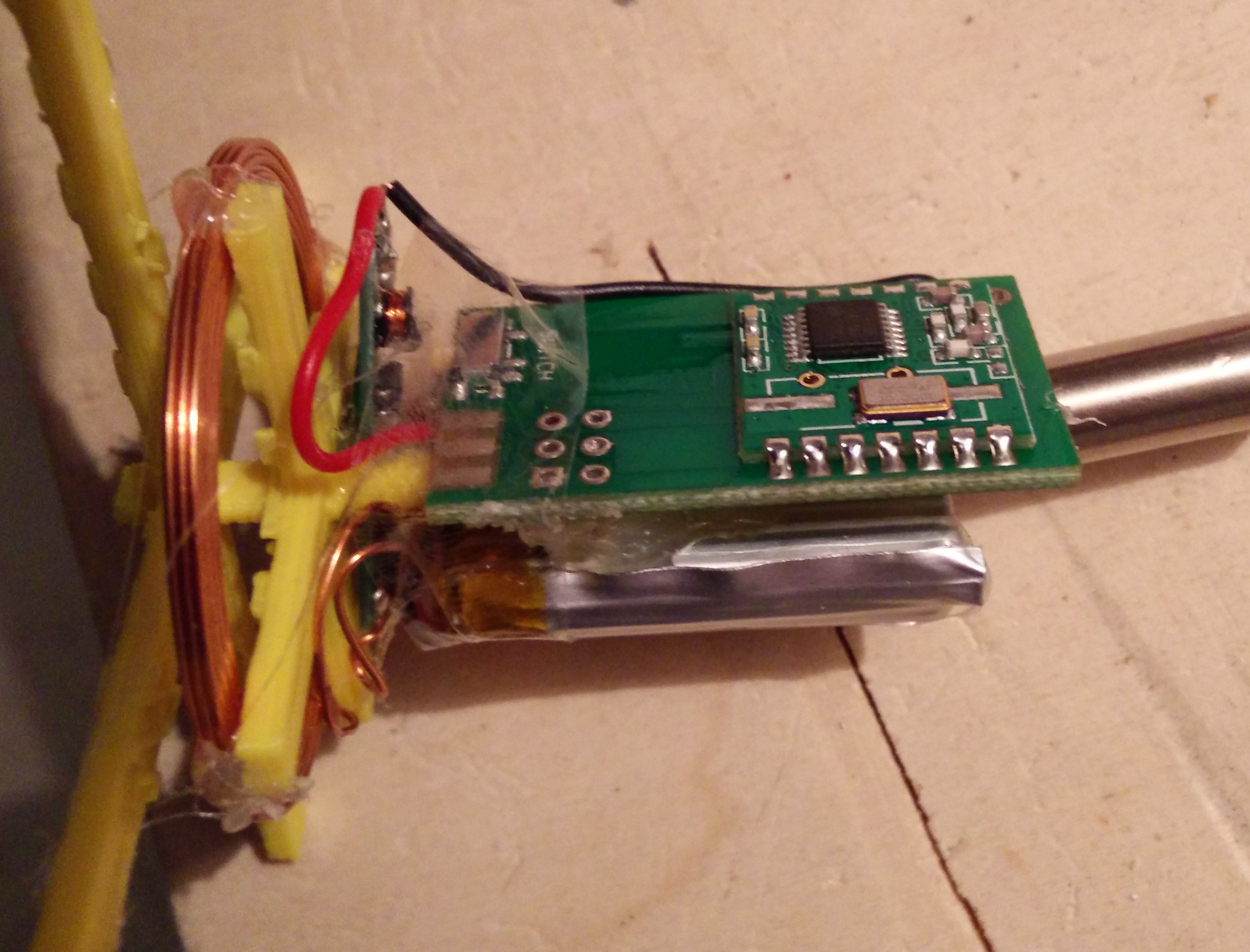


![IMG_20150901_211915[2]](https://bodyinteraction.com/wp-content/uploads/2015/09/img_20150901_2120102.jpg)
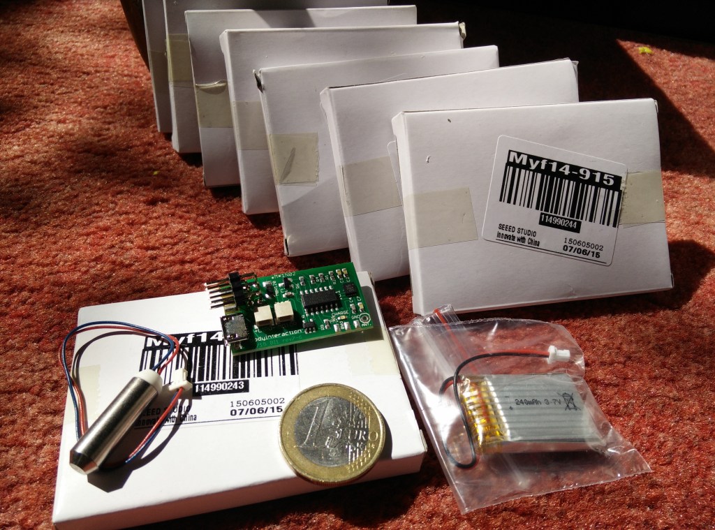
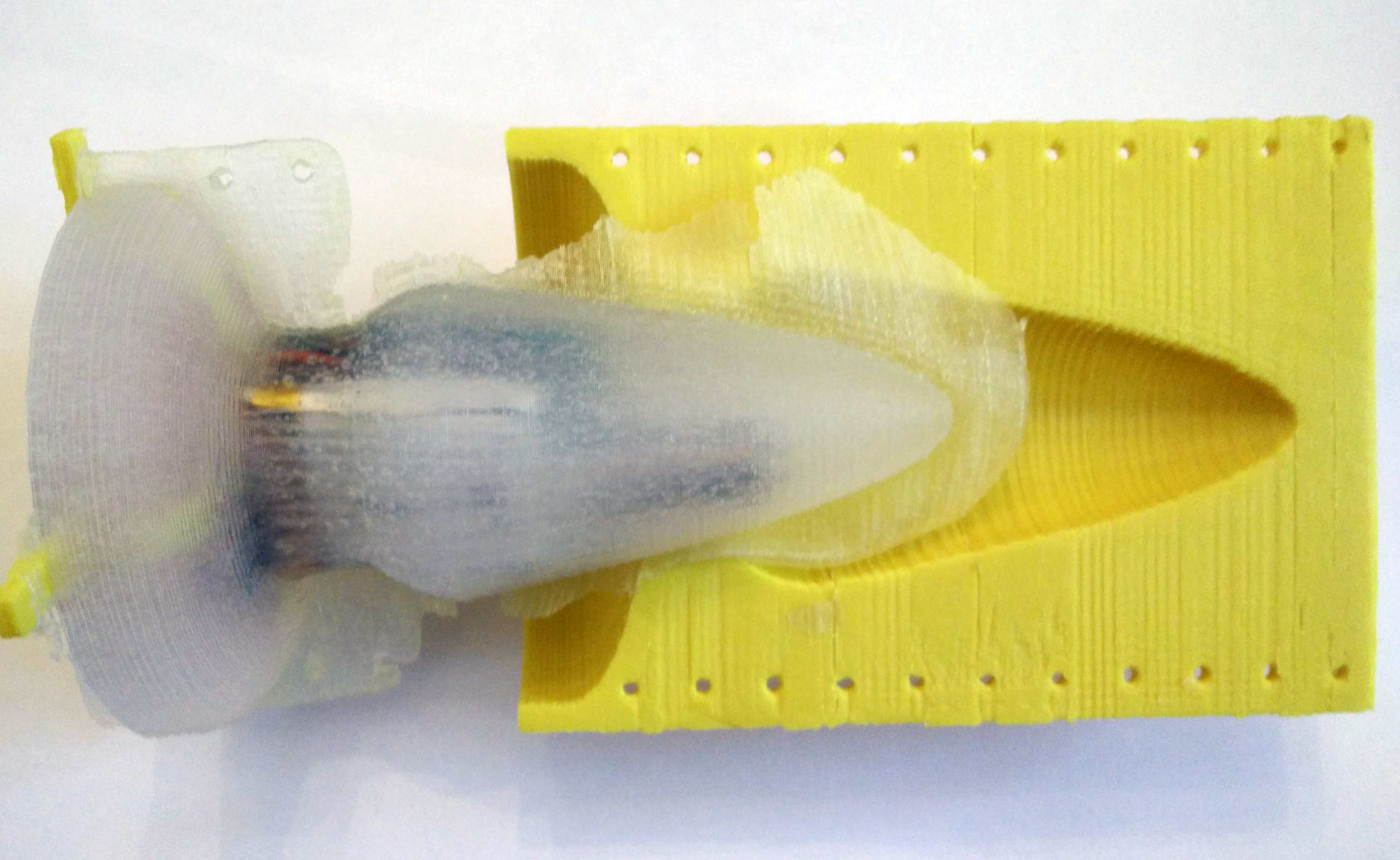
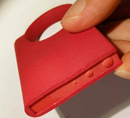
![IMG_20150901_212010[2]](https://bodyinteraction.com/wp-content/uploads/2015/09/img_20150901_2120102.jpg?w=169&h=300) All you need for assembly is the body interaction motion controlled vibrator development board and two M3 screws (about 6mm long).
All you need for assembly is the body interaction motion controlled vibrator development board and two M3 screws (about 6mm long).