
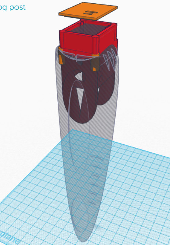
 This is the initial design. The round curved form will be in silicone with vibration motor within (vibration motor not shown on sketch). The red part is 3d printed. It is the enclosure for the body interaction vibrator development board and LiPo battery. You can plug-in the Micro USB connector for battery charging. In addition there is an on/off switch e.g. for travelling.
Update for “balls revisted” – silicone molded vibrator
 The “ball revisited” silicone molded vibrator uses a wireless charging module. Unfortunately there are different version available. The version with some textile like cable jackets have a different inner radius of the receiver coil.
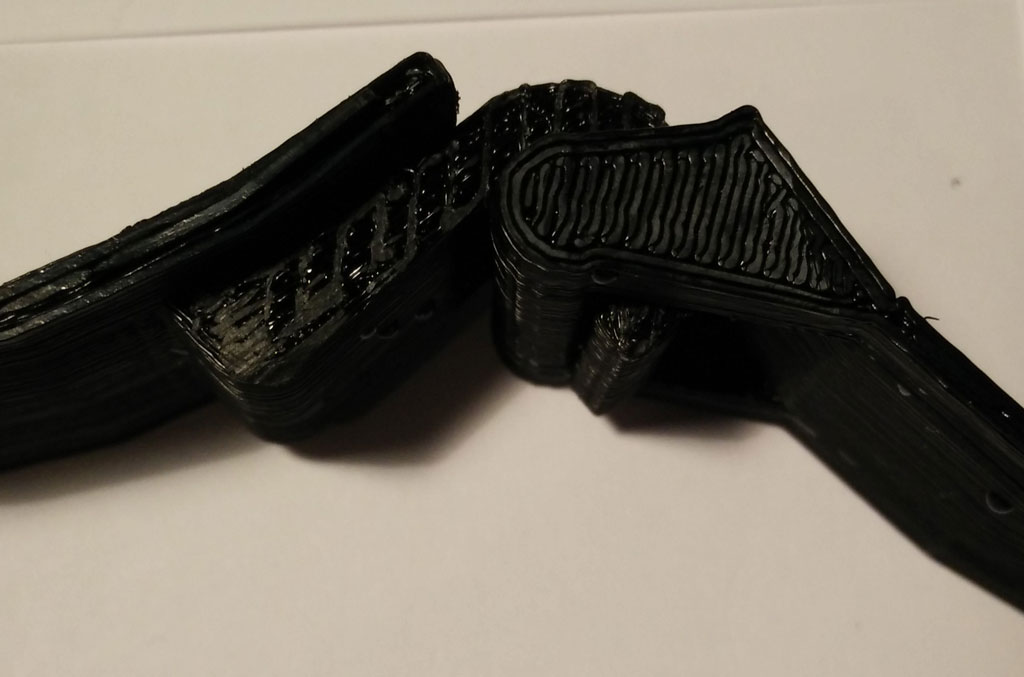
 We have changed the mounting on top of the picture as this type of the receiver coil needs a little more space. In addition the encasement is a bit larger.
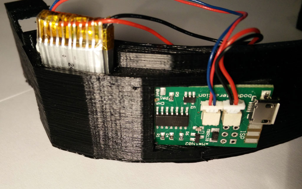
  There is enough space for the body intercation board (top), wireless charging board (right) and the LiPo battery (below).
 Finally the wire of the vibration motor is glued in the middle of the encasement.
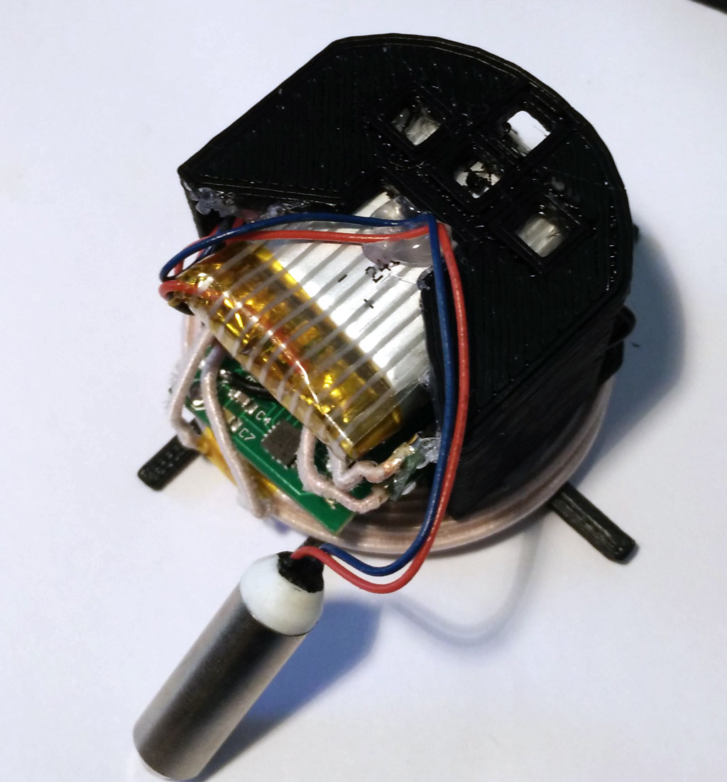 Please follow the “old” instruction – nothing has changed. When printing out the 3d parts use the new version 4 of the inlay. All 3d printing STL files at Thingiverse
Connecting a servo motor – move your vibrator
The body interaction vibrator development board can be connected with additional sensors and actuators. In this post we show how to connect a servo motor. A servo motor can adjust its shaft to be positioned in varies angles. We use a inexpensive SG92R servo which can be positioned in any position between 0° and 180°.
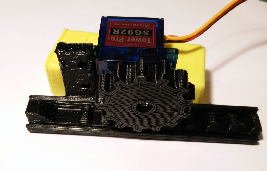 Now we can build eg. a linear actuator which could be useful for sex toys. If you have a 3d printer you can build your linear actuator and fix the servo motor. You can download the design here.

Connecting servo motor and body interaction vibrator development board
The servo motor has 3 wires: ground (-) (black or brown wire), power (+) (red wire) and control (yellow or orange).
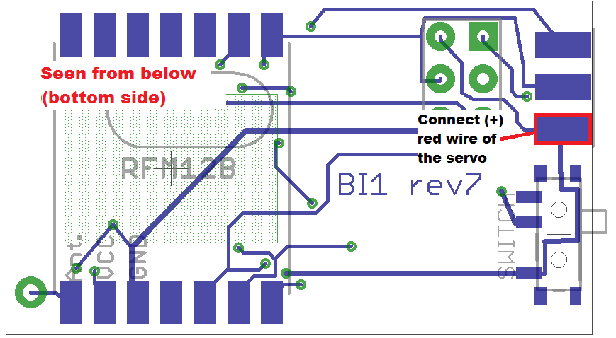
 Connect the (+) wire to the body interaction board. You can use the pad on the bottom side as shown on the image.

 Then turn the board around to the top side. Now you can solder the black wire to the “GND” (ground) pad. Then solder the orange or yellow control wire to the leftmost pad “PA1”.
Programming the servo motor
The standard Arduino servo library will not work on the body interaction board. But you can use the TinyServo library. Download the library as *.zip file here or here and read the forum post.
Go into the Arduino library manager and include the ZIP file. Please restart Arduino.
The following script attaches the servo motor and shows how to control it.
// servo control with the body interaction development board using the TinyServo library
// -- adaption of the demo script by
// tylernt@gmail.com's ATTiny Hardware Timer Assisted Servo Library v1.0 20-Nov-13
// http://forum.arduino.cc/index.php?action=dlattach;topic=198337.0;attach=71790

#include <TinyServo.h>
const byte SERVOS = 1; // number of servos is 1
const byte servoPin[SERVOS] = { 7 }; // servo is connected to PA1 which is pin 7
#define SERVO 0 // our servo is given the name "SERVO"

void setup() {
  setupServos();
}

void loop() {
  delay(1000);
  moveServo(SERVO, 180); // move servo to 180°
  delay(1000);
  moveServo(SERVO, 0); // move servo to 0
  delay(1000);
  for (int i = 0; i <= 180; i++) {
    moveServo(SERVO, i); // move servo from 0° to 180° in 1° steps
    delay(50);
  }
  moveServo(SERVO, 0); // move servo to 0°
  delay(1000);
}
Silicone overmolded vibrator – balls revisited
 Building your own silicone molded vibrator becomes now easier. We already have presented 3d printed forms for building your personal vibrator (massage wand, wireless charged vibrator). The vibrator uses the body interaction vibrator development board. The body interaction board has a Arduino compatible microcontroller, vibration strength control by motion, a vibration motor and a rechargeable battery.
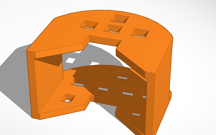 What is new? The electronics including battery are in the base of the vibrator. We developed a 3d printed enclosure for the electronics. This has several benefits: The assembling of the electronics and the molding itself is easier as everything is fixed within the enclosure. And it is more safe as the enclosure shields the electronics from the environment (and vice versa). In addition we used a different charging module from Seeed Studio. The input voltage is only 5V. Now you can connect the charging module with a USB connector and don’t need another power supply. (Look here for an explanation of wireless charging sender and receiver.)

Another improvement is the placing of the vibration motor. The vibration motor can now be placed in the center of the vibrator and it different heights. Just were you need the power.
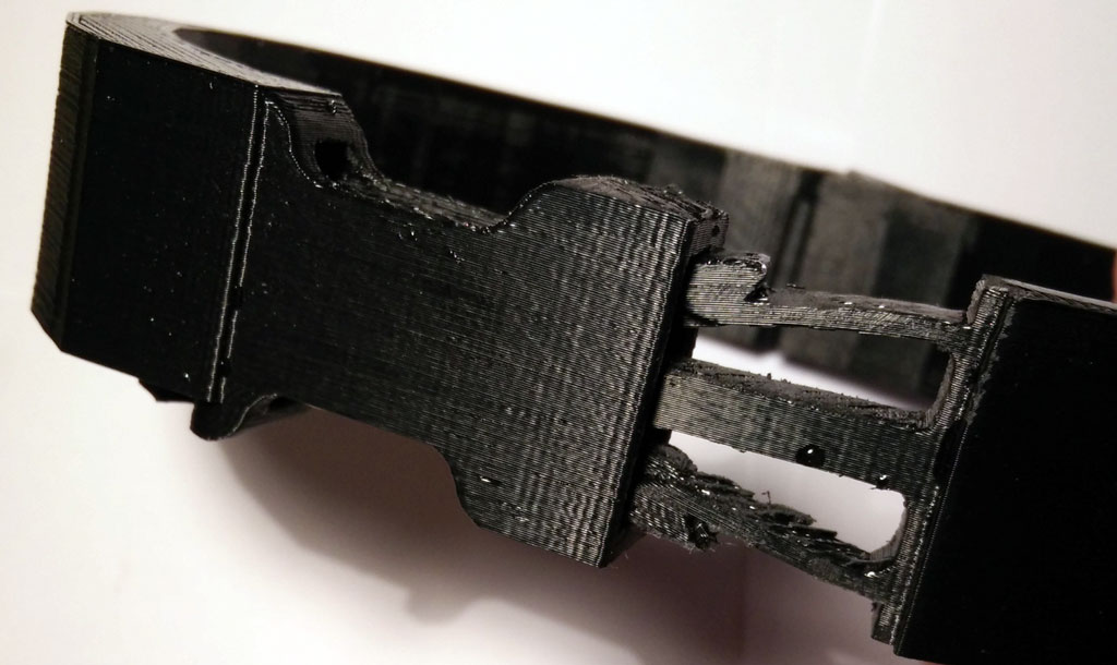
 Finally the mounting is improved. The mounting holds the enclosure when it is inserted into the form.
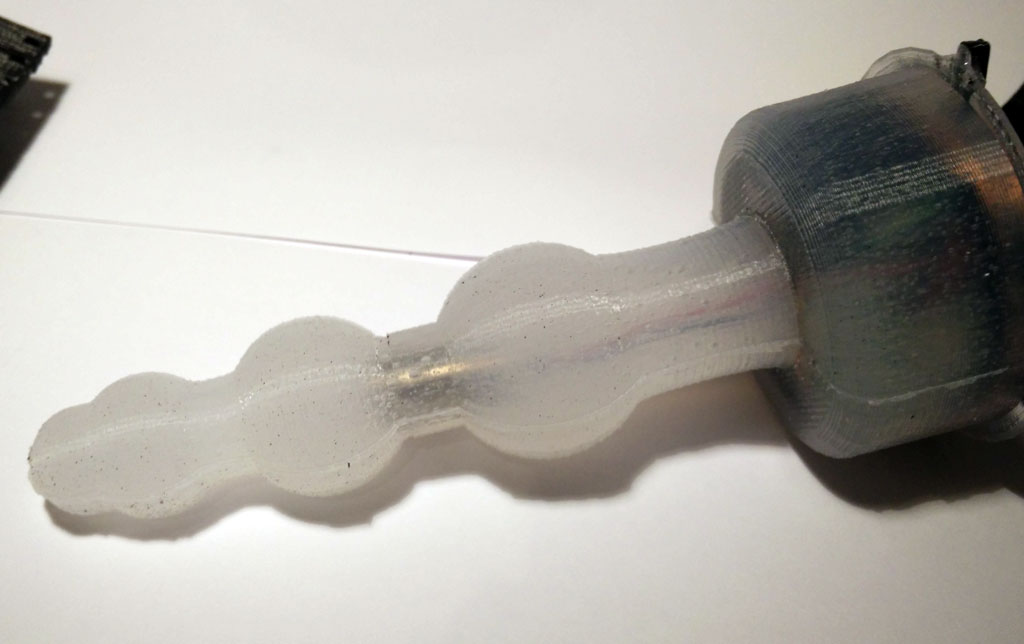
 The mounting (together with the enclosure with the electronics) is inserted into the form. The form consists of two parts which must be fastened together by tinker wire. It is a variation of the ball theme.
We present a step by step procedure for tinkering the vibrator. You need:
- 3d printed form (molding form, 2 parts)
- 3d printed enclosure
- 3d printed mounting
- body interaction vibrator development board
- silicone with a high shore A value (eg. shore A 45 which is quiet hard but still flexible), approx. 100 ml
- wireless charging module eg. from Seeed studio
- soldering station, (hot) glue
Step by step procedure:
A. Print out all forms. You can download the forms from Thingiverse.
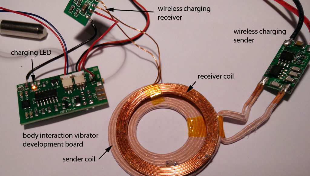
B. Connect the wireless charging module to the body interaction vibrator development board.
B.1 You have to solder a wire connecting (-) on the wireless charging module and GND on the body interaction board.
B.2 Now comes the tricky part. You have to connect (+) from the charging module with the body interaction board. Solder a wire at (+) of the charging module. But where do you solder the wire on the body interaction board? Unfortunately the wireless charging option was not taken into consideration during the development of the board. So there is no appropriate connection on the board.
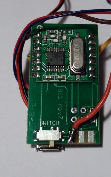
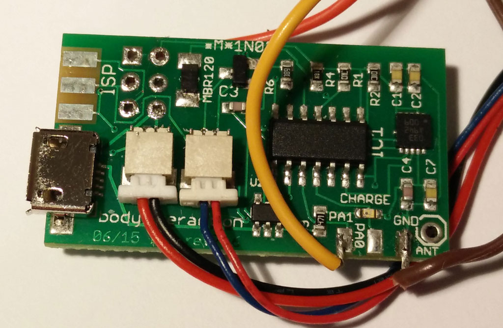
 The best solution is to unsolder the USB connector and connect to + of the USB connection. The easiest way to unsolder the surface mounted USB connector is done with a hot air soldering station. Alternatively you can solder the wire directly to the MAX1555 module – this solution is presented here. In any case: Be careful not to break the tiny pads connecting pcb and USB connector.
B.3 Connect the sender module with a 5V power supply. You can use a USB cable, dismantle the cable and connect the black and red wires.

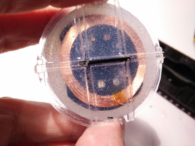
C. Place the receiver charging coil on top of the enclosure. The diameter of the top side is a bit larger than the diameter of the bottom side. Use some glue to fix the coil. Don’t fix the mounting now. It is easier to do it later (step E).
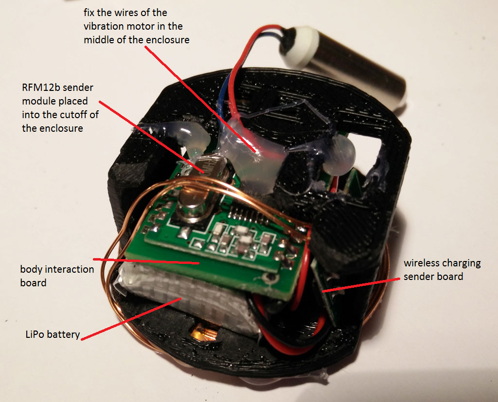
D. Put the electronics into the enclosure: Begin with the body interaction board. The RFM12b is quite large so place it at an outer position. Then insert carefully the LiPo battery. Don’t force it! The plugs for the battery and the motor could break. If you have done so insert the tiny wireless charging receiver board. At the end fix the wires of the vibration motor in the middle of the enclosure.
E. Connect the mounting with the enclosure. There are 2 holes provided where the mounting fits into the enclosure. Use some glue to stick together both parts. (see picture above step C).

F. Put together both parts of the molding form. Use tinkering wire to attach both parts tight together. Then insert the enclosure into the form. Check the wireless charging function. The yellow LED must be on when you place the charging coil over the receiver coil.

G. Now poor silicone into the molding. We use Shore A 45 silicone which is rather hard. The silicone has to dry for some hours or days. Read the instructions of your silicone provider.

H. When the silicone is hard, you can remove the tinkering wire. Then carefully remove the form.


I. Remove the overhang.
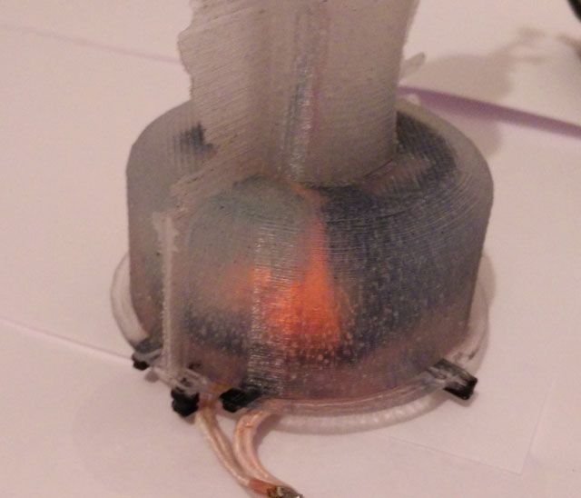
J. Test the wireless charging. The orange LED must be on when both coils are near together.

K. Remove the mounting.
Design your own forms using Tinkercad. Start now and share!
Old versions of the enclosure:Enclosure & mounting togther, Enclosure , Mounting
Download the STL files for 3d printing from Thingiverse.
Update 2016/03/12: Added image of circuits showing where to solder the wireless charging module.
Update 2016/04/05 redesign of mounting and enclosure due to different versions of the wireless charging receiver coil
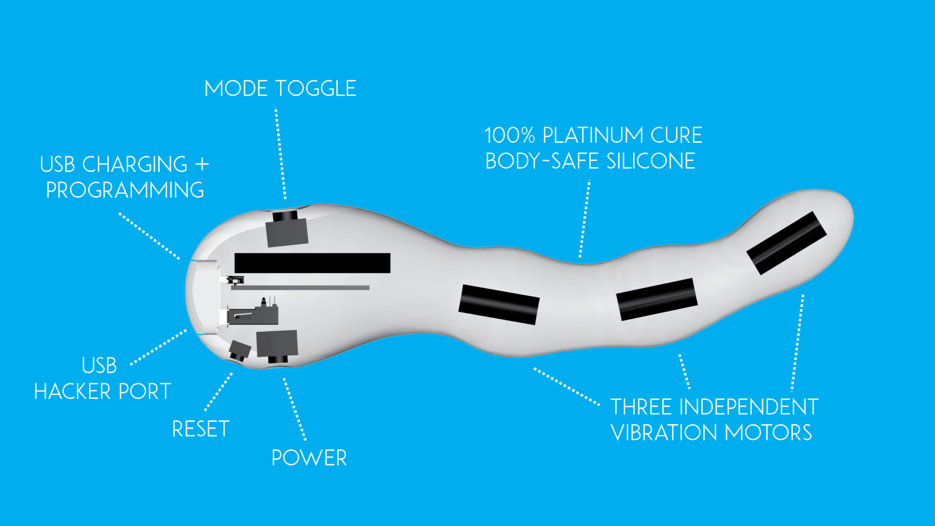
New molded silicone Vibrator – wireless interaction & charging

Preview of the new silicone vibrator designed by bodyinteraction –
wireless charging and wireless communication – Arduino based – programmable
Open source dildo the MOD is cancelled
 Comingle – the only open source sex toy company so far – announced the cancellation of the MOD. The Mod is an open source hardware dildo based on the Arduino platform. In their Indiegogo campaign they gathered 60000$ to produce a dildo made of silicone. The reason among others are patent trolls Comingle says. Read hear and here about the background of the proclaimed patent infringements. These are bad news especially as Comingle is the only sex toy company based on open source software and hardware. In addition they were active (or maybe part of) the US DIY and Maker scene – eg they offered free workshops for everyone.
 You can still find a lot of great tutorials about tinkering dildos, programming the MOD, interfacing with Nunchucks and a lot of more real innovative ideas on the Comingle website – in some aspects much more advanced than anything available on the commercial market. Hopefully they will continue to produce the Dilduino development board – look here and here for a review.
Another interesting aspect is the crowdfunding of sex toys – some companies were quiet successful:
http://motherboard.vice.com/read/what-happened-to-the-crowdfunded-sex-toy-revolution
If you are interested in this topic, look at metafetisch – the best source for sex tech state of the art:
Programming Tutorial part 4: Sinus

Nervous Optic by Ben Felten, CC BY-ND 2.0
In tutorial 3 – “ramps” we learned how to repeat instructions again and again using the for statement. In this tutorial we need the for loop again, bur instead of changing the motor speed by a constant value we want a more dynamic behavior. Therefore we use the sinus function – a classical pattern used for controlling vibrators.
Here is a straight forward approach:
for (float i = 0; i < 20000; i = i + 0.05) {
  analogWrite(motor, (sin(i)); //motor speed set to sin(i)
}
delay(20);
We are changing the variable i in small steps of 0.05. So the variable i will become 0, 0.05, 0.1, 0.15, 0,2 … and so on.
But this doesn’t work. Let’s have a look at the sinus function. Just use the google search and type in “sin(x)”. You will see the following curve:
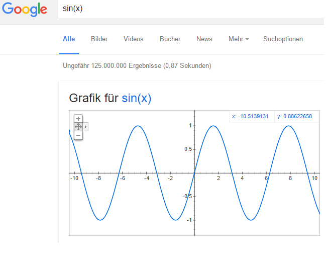
There are two problems:
- There are values below 0 (on the vertical or y-axis). If the value is 0 or below 0 the motor is off.
- The maximal value is 1. But we need values between the minimal motor speed (around 40) and the maximal speed (always 255).
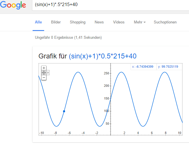
You can try to adjust the function and visualize it with google search. Maybe you will discover an interesting variant of the sinus curve.
We use the following function:
(sin(x)+1) 0.5 * (maximal motor speed – minimal motor speed)) + minimal motor speed
- Sin(x)+1: add 1 to get positive values only between 0 and 2 instead of -1 and 1.
- Multiply by 0.5: get values between 0 an 1 instead 0 and 2
- Multiply with maximal motor speed (255) – minimal motor speed (40): values are now between 0 and 215
- Add minimal speed: values are between 40 and 255. So the motor will always be on.
This is the script. Please have a look at tutorial 2 if you don’t know how to upload the script.
 // www.bodyinteraction.com tutorial sinus
int motor = 3;
int minimal_motorspeed = 50;

void setup() {
  pinMode(motor, OUTPUT);
}
void loop() {
  for (float i = 0; i < 20000; i = i + 0.05) {
    analogWrite(motor, ((sin(i) + 1) * 0.5 * 215) + 40);
    delay(5);
  }
}
If you want to slow down the changes in the motor speed change delay(5) and take larger values.
Go back to tutorial 3: ramps
Vibrating 3d Printed Necklace
 There are a lot of sensible areas of the body which are also erogenous zones (see Wikipedia). The neck is one of them. Stimulation can be achieved eg. by licking and kissing. The stimulation can be quite strong. So why not try to stimulate your neck with vibration? We think it works.
Think of an artistic designed necklace or collar with a vibration function. The vibration will be turned on when you move and gets more intense when you shake our head eg. while dancing. Or the vibration function will be turned on remotely by your friend.
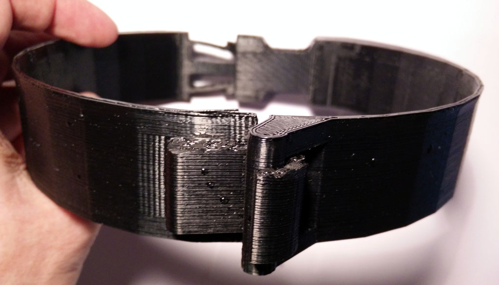
 Body interaction has made a 3d design for a vibrating necklace. It can be secured by a solid clip closure at the back of the neck. At this place the vibration motor is positioned which gives an intense vibration especially at the back of the neck but also at the whole neck.
 The body interaction vibrator development board is inserted into the collar. It controls the vibration motor. The more you move the more it vibrates. There is also place for the battery. Wires and boards can be hidden. Unhidden it has a scifi look-alike.
 In the front there is a solid but easy to close hook closure.
Download 3d files from Thingiverse and print it.
Get the vibrating electronics from Tindie.
Edit and design your own with Tinkercad https://tinkercad.com/things/8stCwczMAkp

Programming the body interaction 1 – part 3 – ramps
Ramps

In this tutorial the continuous change of the vibration motor speed is regarded. Typical vibrator pattern are ramps. They start at a given value. Then the motor speed is continuously changed. The values could be increasing or decreasing.
In our example we have two ramps.
- Increasing ramp: It starts with the minimal motor speed (40). The vibration is slowly increased up to maximal speed (255).
- Decreasing ramp: It starts with maximal motor speed and decreases very fast until minimal motor speed is reached.

We will achieve this by using the for statement.
for (int i=minimal_motorspeed; i <=255; i++) {
  analogWrite(motor, i);
  delay(10); // wait for 1/100 second
}
The code after the for statement will be repeated so long a condition remains true.
- int i =minimal_motorspeed: a new local variable i is introduced and given the value of minimal_motorspeed (40)
- i <= 255: this is the condition – until the variable is below or equal 255 the code will be executed
- i++: each time the code is executed the variable i will be increased by 1
The values of i are 40, 41, 42, 43, … , 255. We use the variable i to change the motor speed. The speed of the motor will be changed at each iteration. So the motor speed will be set to 40 (which is the minimal speed), 41, 42, …, 255 using the following statement:
analogWrite(motor, i);
The delay statement changes the pitch of the ramp. If the delay time is high the pitch will be low:
delay(10);
The following code will realize the function visualized above. You can change the pitch by adjusting the delay time.
// www.bodyinteraction.com tutorial ramp
int motor=3;
int minimal_motorspeed=40;
void setup() {
  pinMode(motor, OUTPUT);
}
void loop() {
  for (int i=minimal_motorspeed; i <=255; i++) {
    analogWrite(motor, i);
    delay(10);
  }
  for (int i=255; i > minimal_motorspeed; i--) {
    analogWrite(motor, i);
    delay(2);
  }
  analogWrite(motor, 0); //motor off
  delay(1000);
}
Copy the code to Arduino and try out. In tutorial 2 it is explained how to upload the code to the body interaction 1.
Next tutorial: Classical vibration pattern – the sinus curve
Go back to tutorial acceleration

Ramp to the beach by Danniel Ramirez, CC BY 2.0
Programming the body interaction 1 (BI) part 2

Foto by Kevin Dooley, CC BY 2.0
Reading the accelerometer data
The BI has built in the accelerometer Bosch BMA020. The BMA020 is a 3-axis accelerometer and reads acceleration data in X, Y and Z direction. The accelerometer is used to control the operation of the BI. It captures changes in movement eg. slowing, speed up, change of direction. Steady movement can not be captured. Nevertheless it is possible to calculate the orientation of the BI eg. upright or downright.
To read out the data we use the JeeLib – a great library we will use to control other devices and read out sensors (read here how to install). The library must be included, add:
#include <JeeLib.h>
In JeeLib the accelerometer is called GravityPlug. It is not connected to a pin directly (as the vibration motor). Instead it is connected to the I2C bus, but at this point ignore the details. Just add:
PortI2C myBus (1);
GravityPlug sensor (myBus);
Now we can read out the accelerometer using the name “sensor”.
Now we want to read out the sensor. This is done by adding “.getAxes()” to “sensor”. But before we declare a new variable called p, where we the acceleration in X-, Y- and Z-axis is stored:
const int* p = sensor.getAxes();
The acceleration in x-direction is stored in p[0], y-direction in p[1] and z-direction in p[2].
p[0], p[1] and p[2] are integers. When there is no acceleration (eg. the BI is not moved) the value would be approx 0. If you move it horizontally to the right it will return positive values. If you move it horizontal to the left it will return negative values. (Could be vice versa, it depends on the orientation of the accelerometer).
We introduce 3 new variables x, y and z for storing the values:
int x,y,z;
As we are not interested in the direction of the acceleration we convert negative values to positives. This is known as the absolute value and is computed with the function abs(), see: https://www.arduino.cc/en/Reference/Abs
x = abs(p[0]);
y = abs(p[1]);
z = abs(p[2]);
We also introduce a further variable called “threshold”. Only values above a given threshold will change the behaviour of the vibration motor. This is useful to ignore the gravity which influences at least of the axises.
int threshold = 250;
Now we put everything together. The script should start the vibration motor if there is acceleration either in x, y or z direction above a threshold. Otherwise the motor is off.
#include JeeLib.h;
PortI2C myBus (1);
GravityPlug sensor (myBus);
int motor = 3;
int threshold = 100;
int x, y, z;
void setup() {
pinMode(motor, OUTPUT);
}
void loop() {
const int* p = sensor.getAxes();
x = abs(p[0]);
y = abs(p[1]);
z = abs(p[2]);
analogWrite(motor, 0); //motor off
if (x &gt; threshold || y &gt; threshold || z &gt; threshold) {
analogWrite(motor, 255); //motor on
}
delay(2000); // wait for 2 second
}
Let’s take a further look at the loop. Every time when the instruction in the loop are executed, the sensor will be read out. The absolute values are stored in x, y and z by using the abs() function. Then the motor is set off.
The following statement
analogWrite(motor, 255);
will turn the motor on if the following condition is true:
(x > threshold || y > threshold || z > threshold)
The condition is true when either x > threshold or y > threshold or z > threshold. You can read “||” as logical or. Read more about the if function and boolean operators (or, and, not).
Finally a delay functions stops further processing for 2 seconds. Then the loop will be executed again, starting to read out the accelerometer values.
In depth example of reading the BMA020:
http://playground.arduino.cc/Main/SoftwareI2CLibrary
Jeelib GravityPlug – how to read out the BMA020 with the JeeLib library.
http://jeelabs.org/2010/03/22/gravity-plug/
More about Acceleration and Gyros and how to calculate the orientation:
http://www.instructables.com/id/Accelerometer-Gyro-Tutorial/
Copy the source code (script) into an Arduino window. Then click compile . If everything is ok you get the message done compiling. 
Then upload the code to the body interaction 1. If everything is ok you get the message done uploading. You can ignore the warnings.  But if you don’t get the done uploading message something went wrong. in this case read the following post:
https://bodyinteraction.com/2016/01/08/get-started-with-arduino-1-6-7-and-windows-10/
Go to the next tutorial (part 3): ramps
