Building your own silicone molded vibrator becomes now easier. We already have presented 3d printed forms for building your personal vibrator (massage wand, wireless charged vibrator). The vibrator uses the body interaction vibrator development board. The body interaction board has a Arduino compatible microcontroller, vibration strength control by motion, a vibration motor and a rechargeable battery.
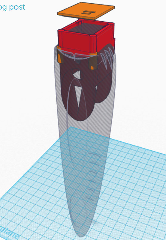
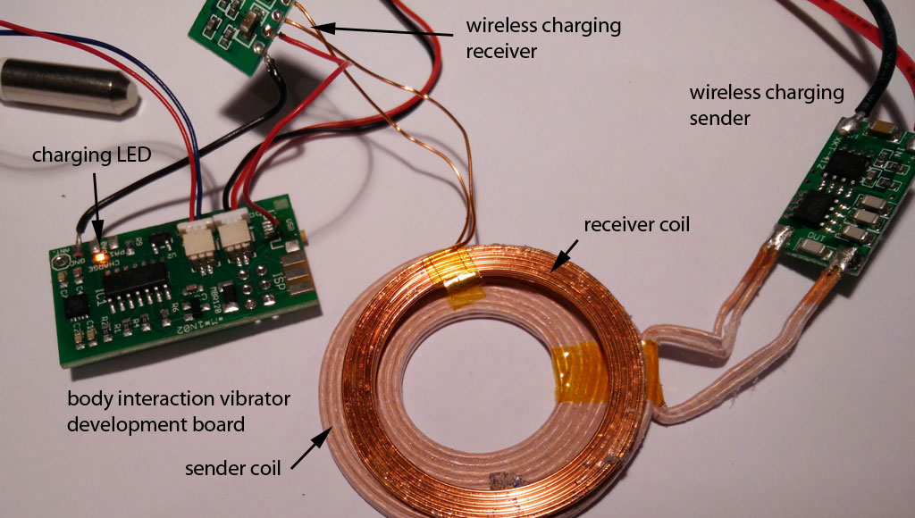
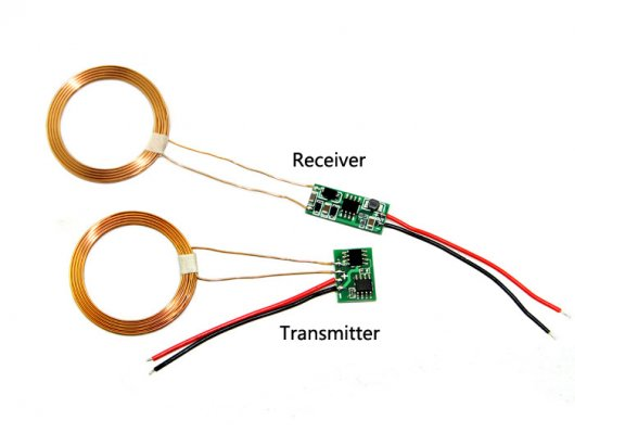
 What is new? The electronics including battery are in the base of the vibrator. We developed a 3d printed enclosure for the electronics. This has several benefits: The assembling of the electronics and the molding itself is easier as everything is fixed within the enclosure. And it is more safe as the enclosure shields the electronics from the environment (and vice versa). In addition we used a different charging module from Seeed Studio. The input voltage is only 5V. Now you can connect the charging module with a USB connector and don’t need another power supply. (Look here for an explanation of wireless charging sender and receiver.)

Another improvement is the placing of the vibration motor. The vibration motor can now be placed in the center of the vibrator and it different heights. Just were you need the power.
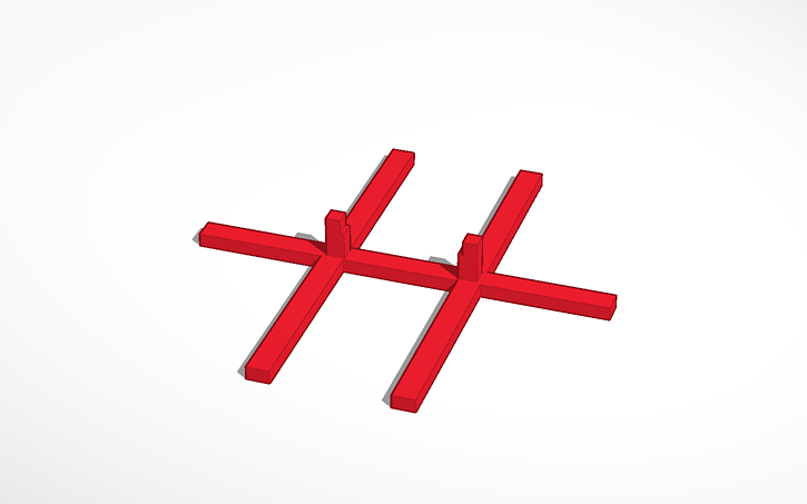
 Finally the mounting is improved. The mounting holds the enclosure when it is inserted into the form.
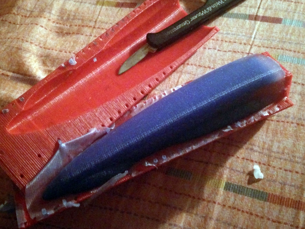
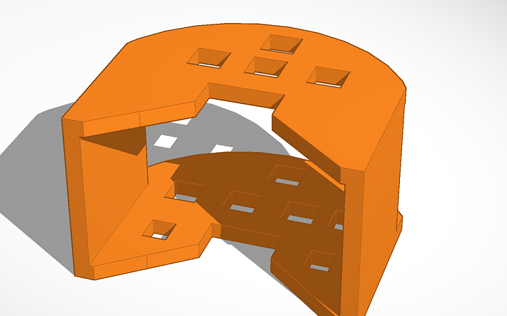
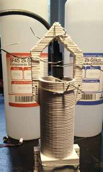
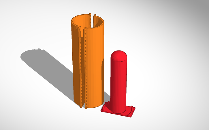
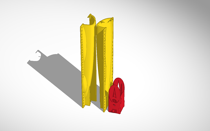
 The mounting (together with the enclosure with the electronics) is inserted into the form. The form consists of two parts which must be fastened together by tinker wire. It is a variation of the ball theme.
We present a step by step procedure for tinkering the vibrator. You need:
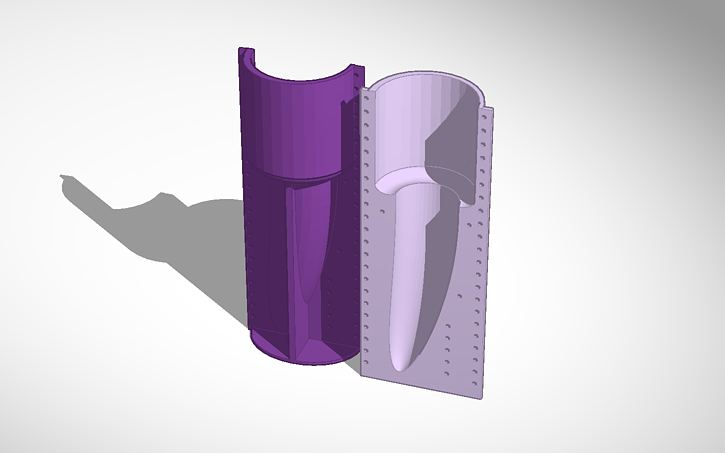
- 3d printed form (molding form, 2 parts)
- 3d printed enclosure
- 3d printed mounting
- body interaction vibrator development board
- silicone with a high shore A value (eg. shore A 45 which is quiet hard but still flexible), approx. 100 ml
- wireless charging module eg. from Seeed studio
- soldering station, (hot) glue
Step by step procedure:
A. Print out all forms. You can download the forms from Thingiverse.

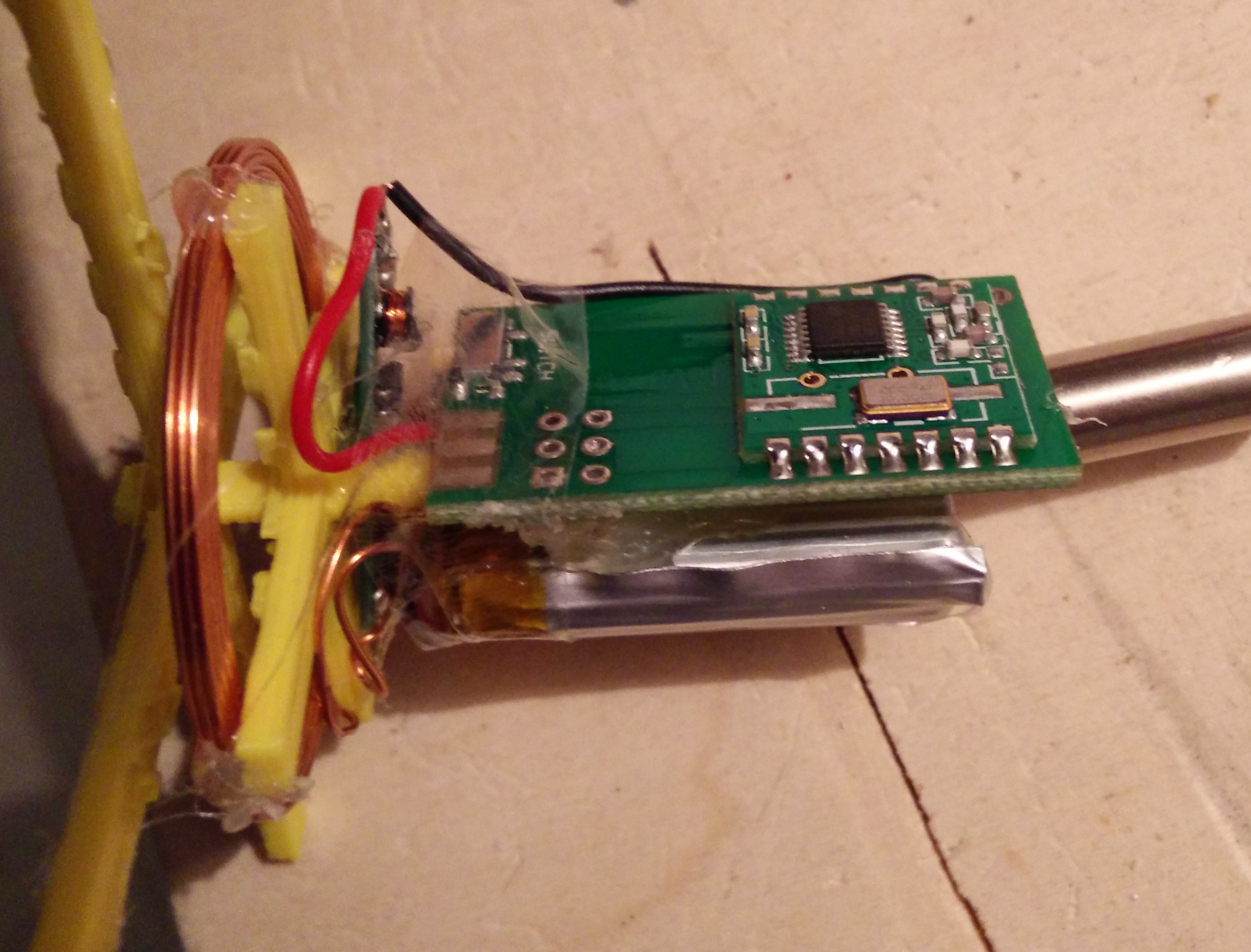
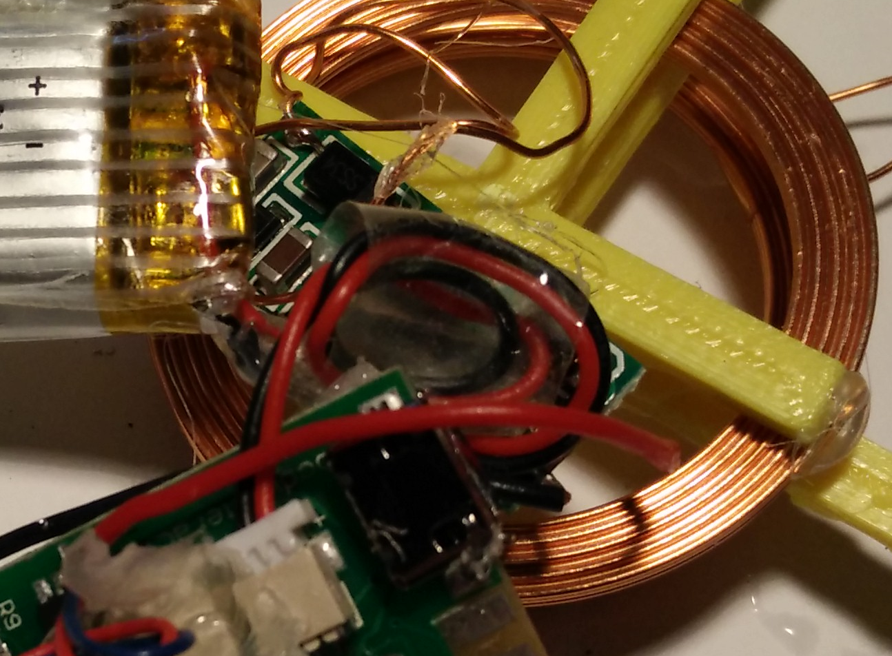
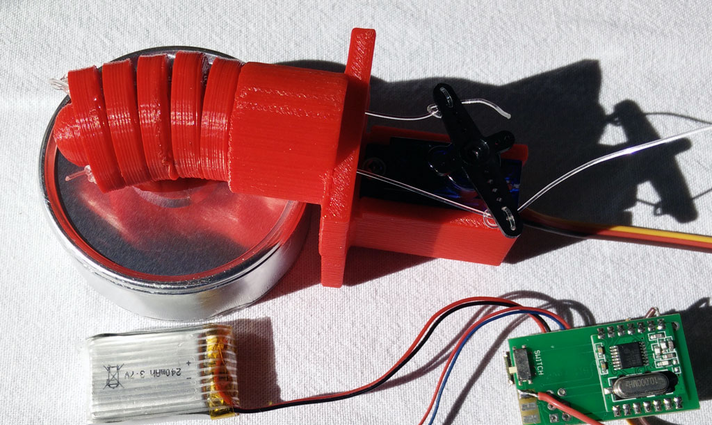
B. Connect the wireless charging module to the body interaction vibrator development board.
B.1 You have to solder a wire connecting (-) on the wireless charging module and GND on the body interaction board.
B.2 Now comes the tricky part. You have to connect (+) from the charging module with the body interaction board. Solder a wire at (+) of the charging module. But where do you solder the wire on the body interaction board? Unfortunately the wireless charging option was not taken into consideration during the development of the board. So there is no appropriate connection on the board.
 The best solution is to unsolder the USB connector and connect to + of the USB connection. The easiest way to unsolder the surface mounted USB connector is done with a hot air soldering station. Alternatively you can solder the wire directly to the MAX1555 module – this solution is presented here. In any case: Be careful not to break the tiny pads connecting pcb and USB connector.
B.3 Connect the sender module with a 5V power supply. You can use a USB cable, dismantle the cable and connect the black and red wires.

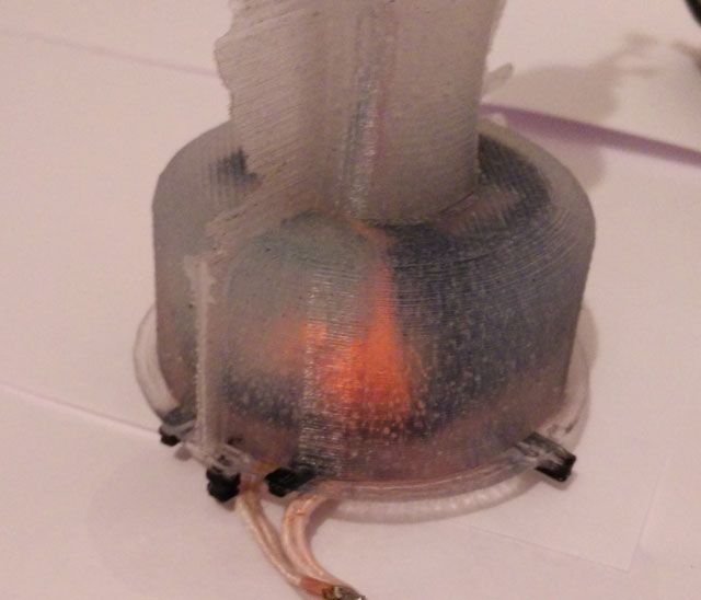
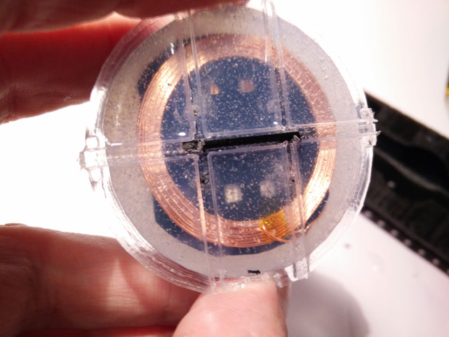
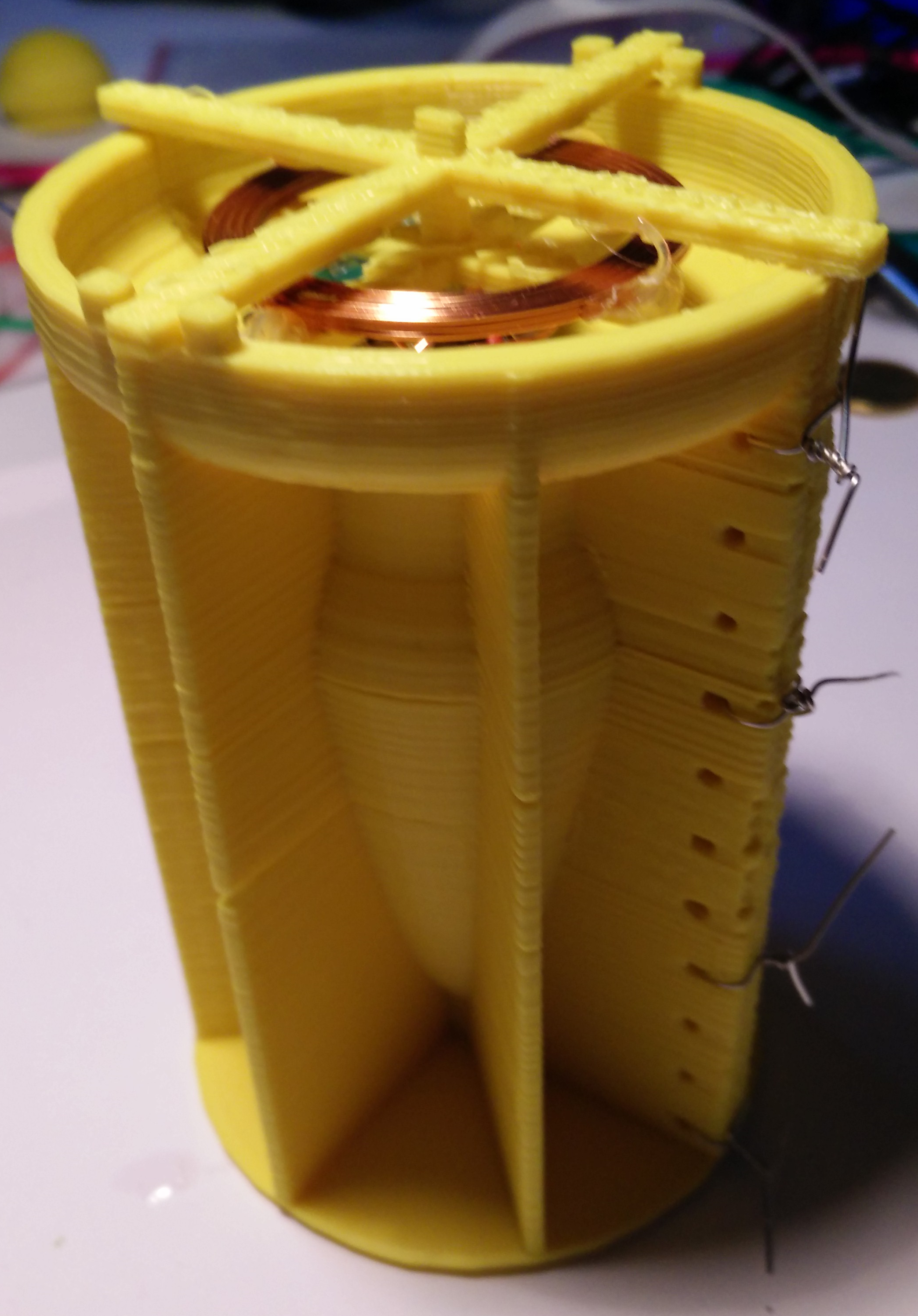
C. Place the receiver charging coil on top of the enclosure. The diameter of the top side is a bit larger than the diameter of the bottom side. Use some glue to fix the coil. Don’t fix the mounting now. It is easier to do it later (step E).
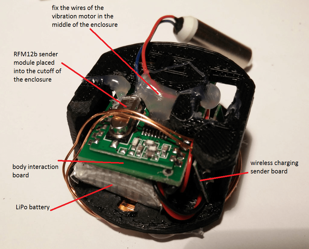
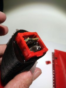
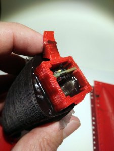
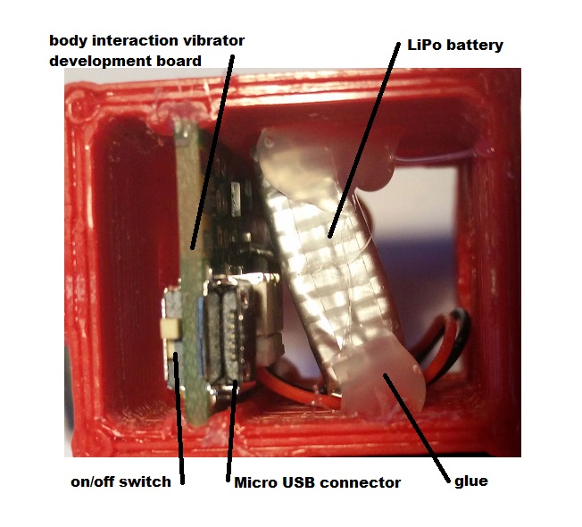
D. Put the electronics into the enclosure: Begin with the body interaction board. The RFM12b is quite large so place it at an outer position. Then insert carefully the LiPo battery. Don’t force it! The plugs for the battery and the motor could break. If you have done so insert the tiny wireless charging receiver board. At the end fix the wires of the vibration motor in the middle of the enclosure.
E. Connect the mounting with the enclosure. There are 2 holes provided where the mounting fits into the enclosure. Use some glue to stick together both parts. (see picture above step C).

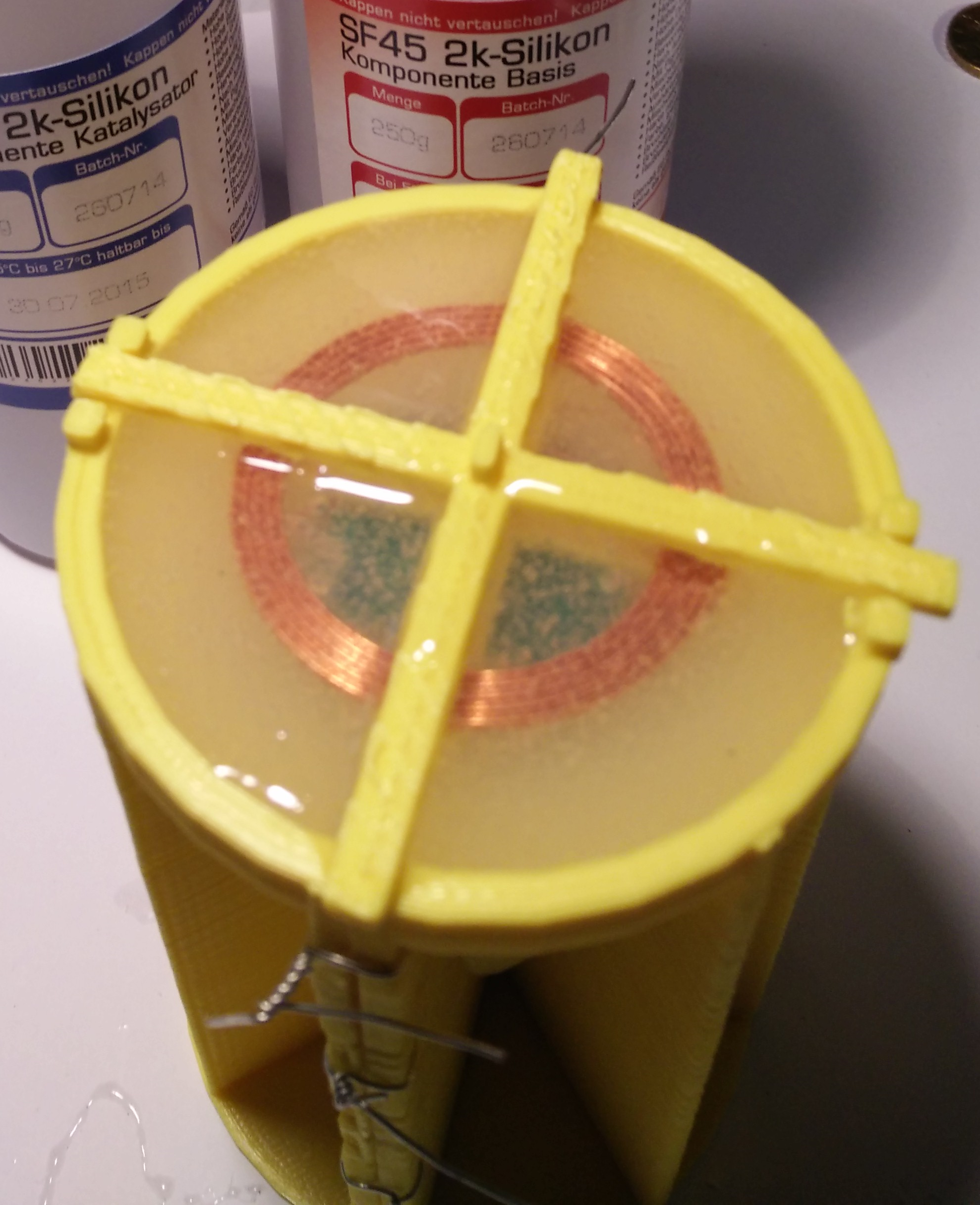
F. Put together both parts of the molding form. Use tinkering wire to attach both parts tight together. Then insert the enclosure into the form. Check the wireless charging function. The yellow LED must be on when you place the charging coil over the receiver coil.

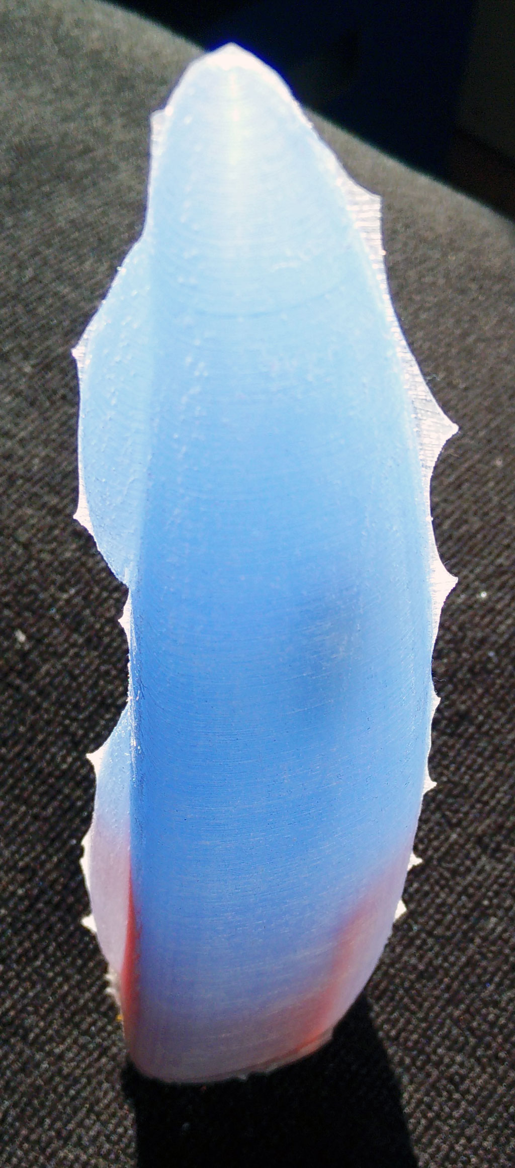
G. Now poor silicone into the molding. We use Shore A 45 silicone which is rather hard. The silicone has to dry for some hours or days. Read the instructions of your silicone provider.

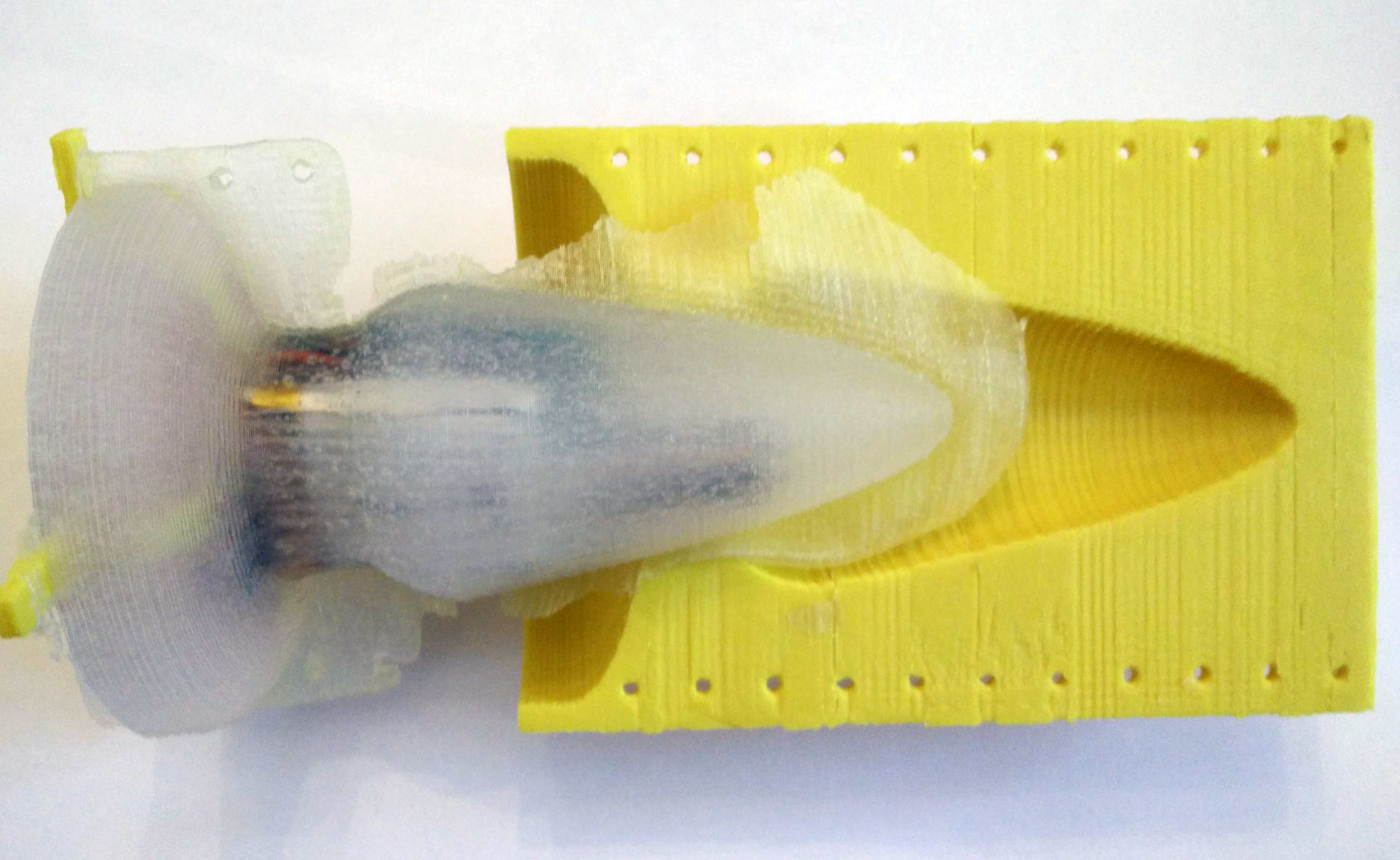
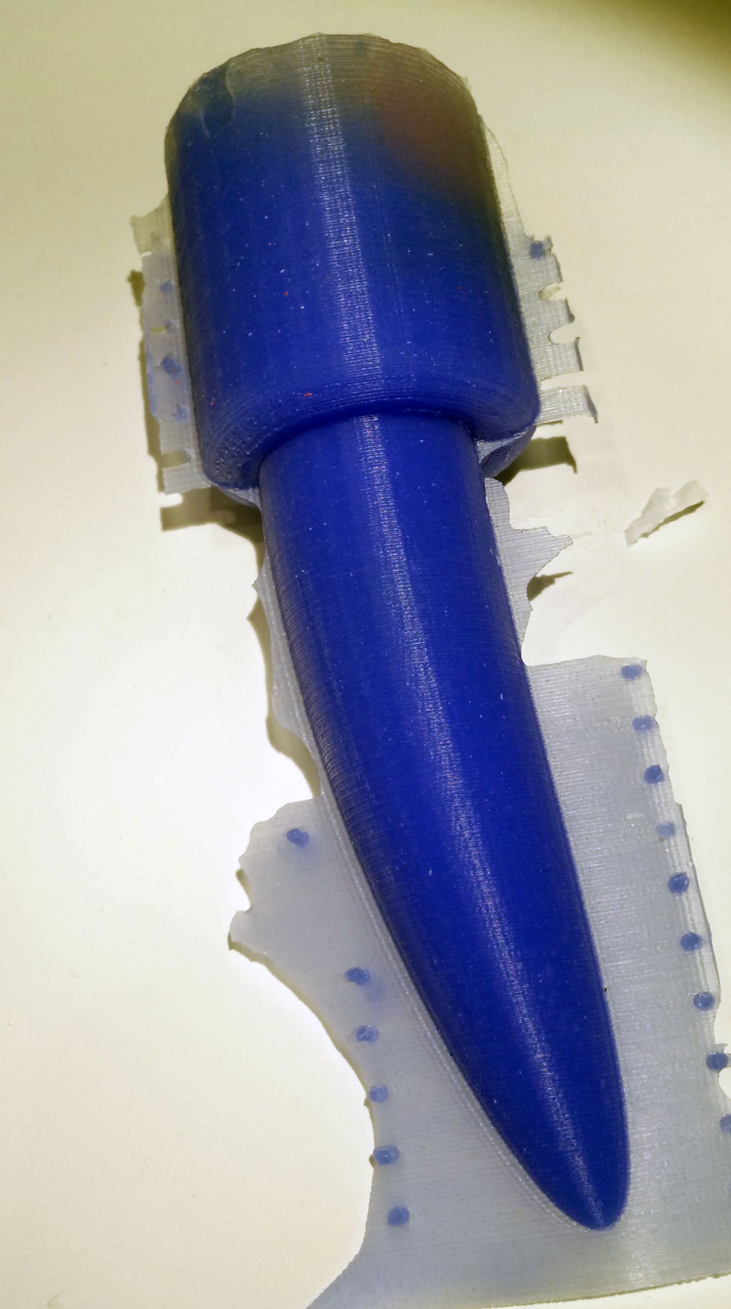
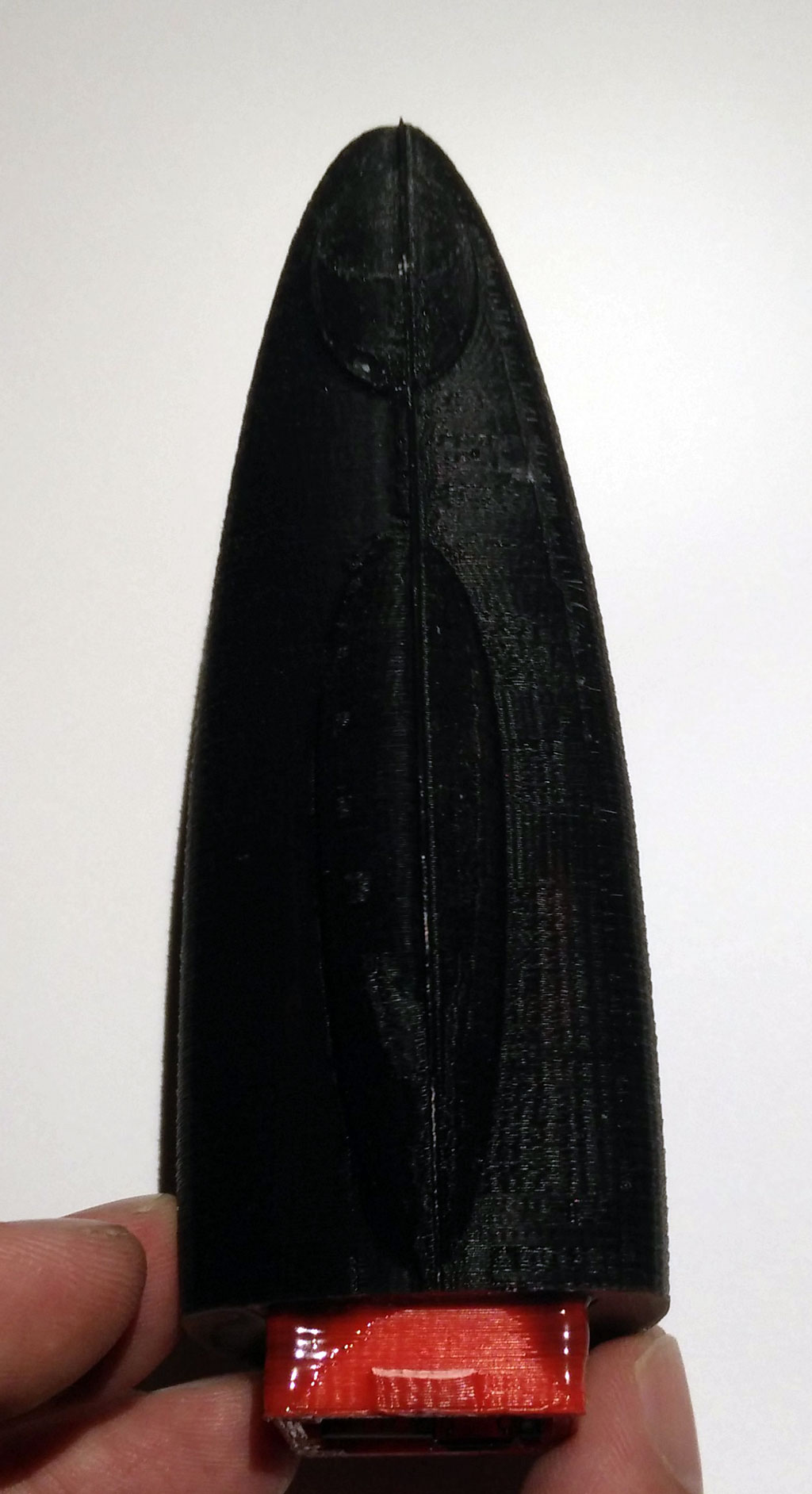
H. When the silicone is hard, you can remove the tinkering wire. Then carefully remove the form.


I. Remove the overhang.

J. Test the wireless charging. The orange LED must be on when both coils are near together.


K. Remove the mounting.
Design your own forms using Tinkercad. Start now and share!
Old versions of the enclosure:Enclosure & mounting togther, Enclosure , Mounting
Download the STL files for 3d printing from Thingiverse.
Update 2016/03/12: Added image of circuits showing where to solder the wireless charging module.
Update 2016/04/05 redesign of mounting and enclosure due to different versions of the wireless charging receiver coil

 In this series of posts we describe how-to make a vibrating sex toy which is part of the Internet of Things.
 Simply put the electronics inside so that the upper body of the switch is on the same level as the upper inlay. We use hot glue to fix the basic node.
 Then fix the receiver coil of the wireless charging module on top of the inlay. The next step is to fix the hanging at the inlay.
 Now fix the LiPo battery on the bottom side of the inlay using hot glue or similar. Fix the wires. Finally you might fix the wires of the vibration motor next to the middle of the LiPo battery.
 Use tinkering wire to fix both parts of the molding form.
 Put the inlay in the form. Fix the hanging with a tape or similar. The motors shouldn’t touch the inner part of the form.
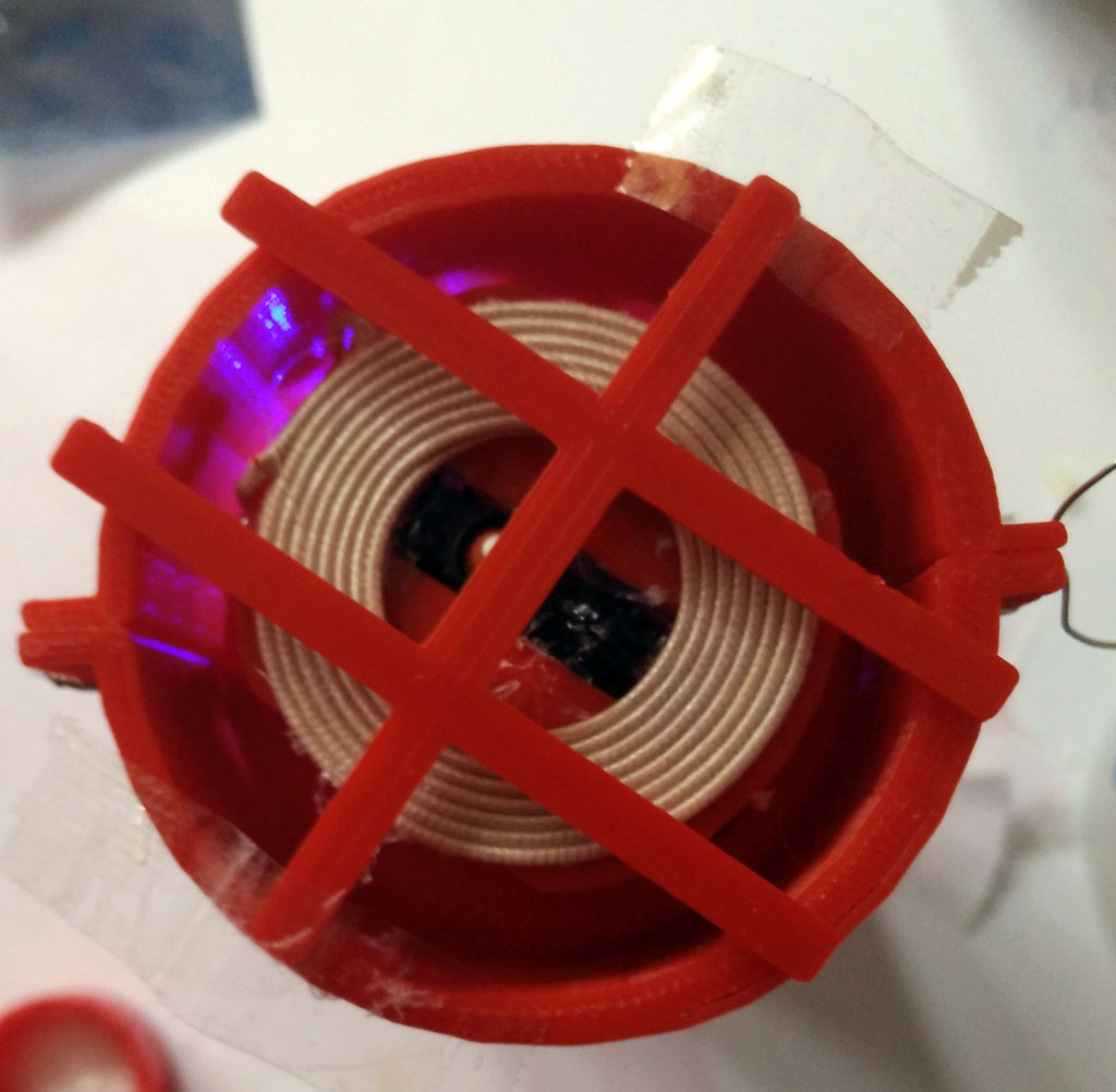 Now prepare the silicone. We use Shore A 45 silicone (approx. 250 ml) from Silikonfabrik.de. It is hard but still a bit flexible. You may add color, too. You have about 10 minutes to stir the silicone and poor it in the form.
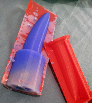

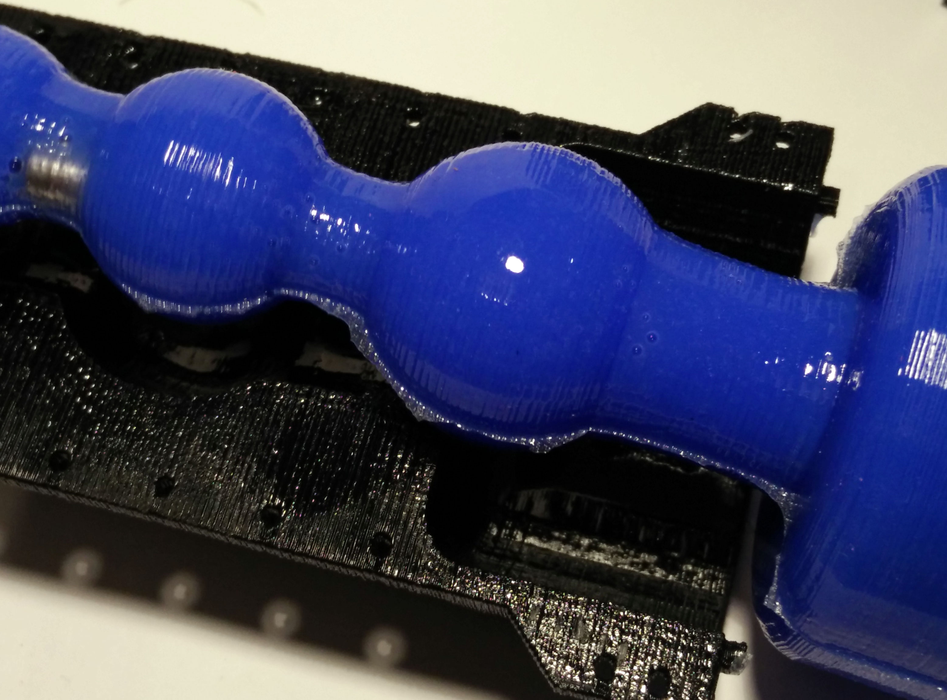
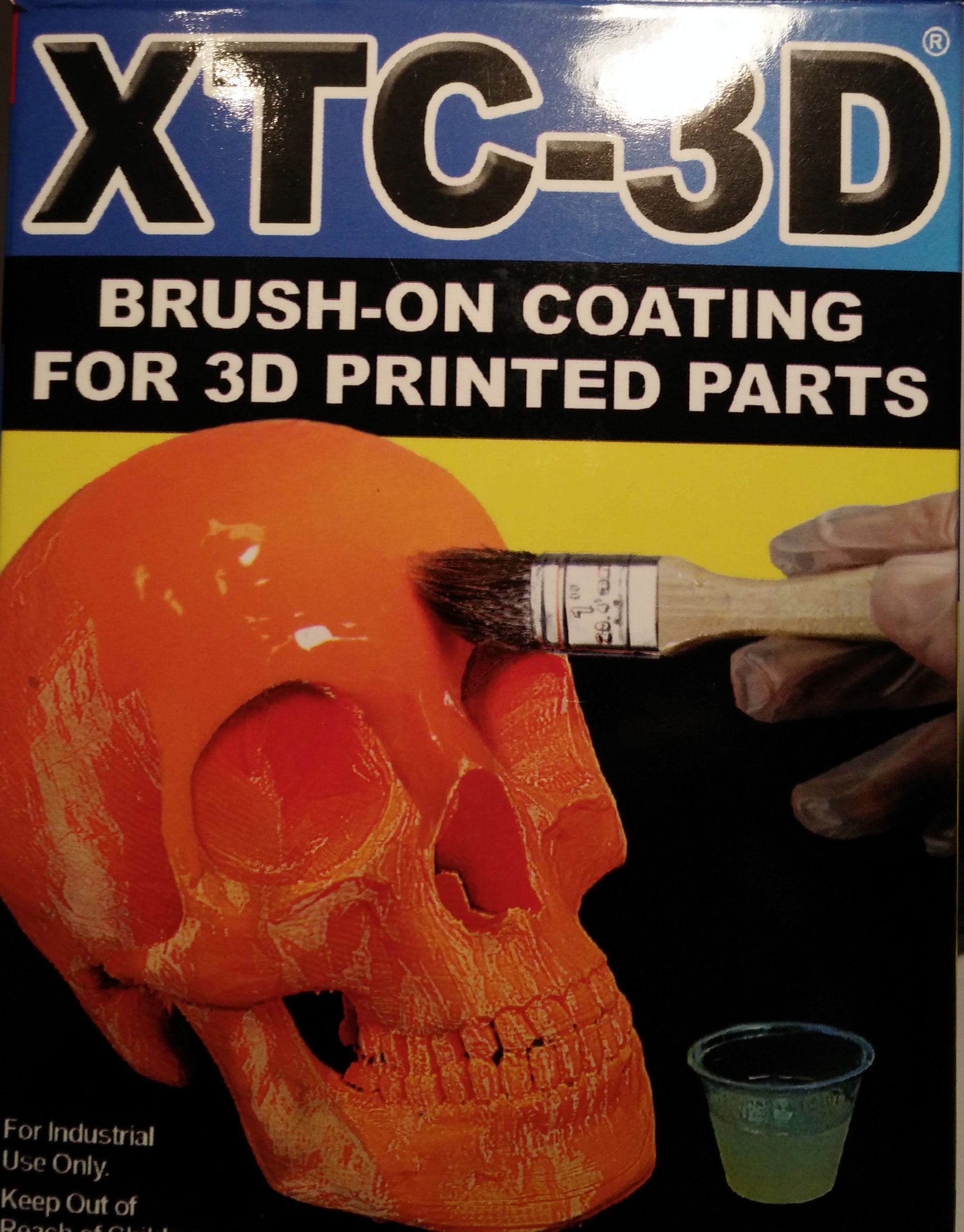
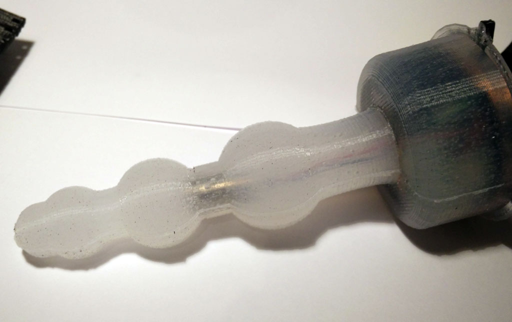
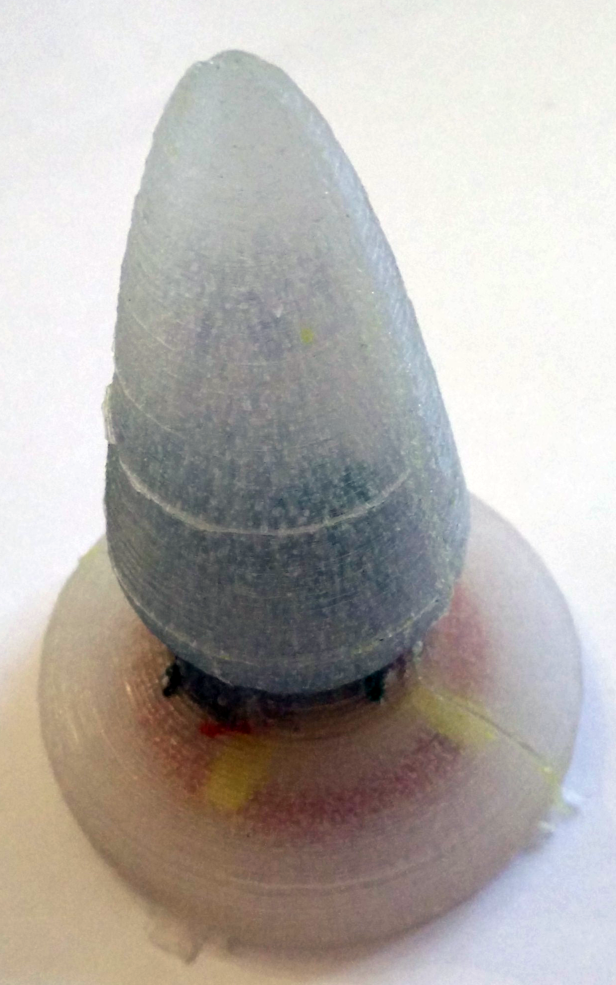
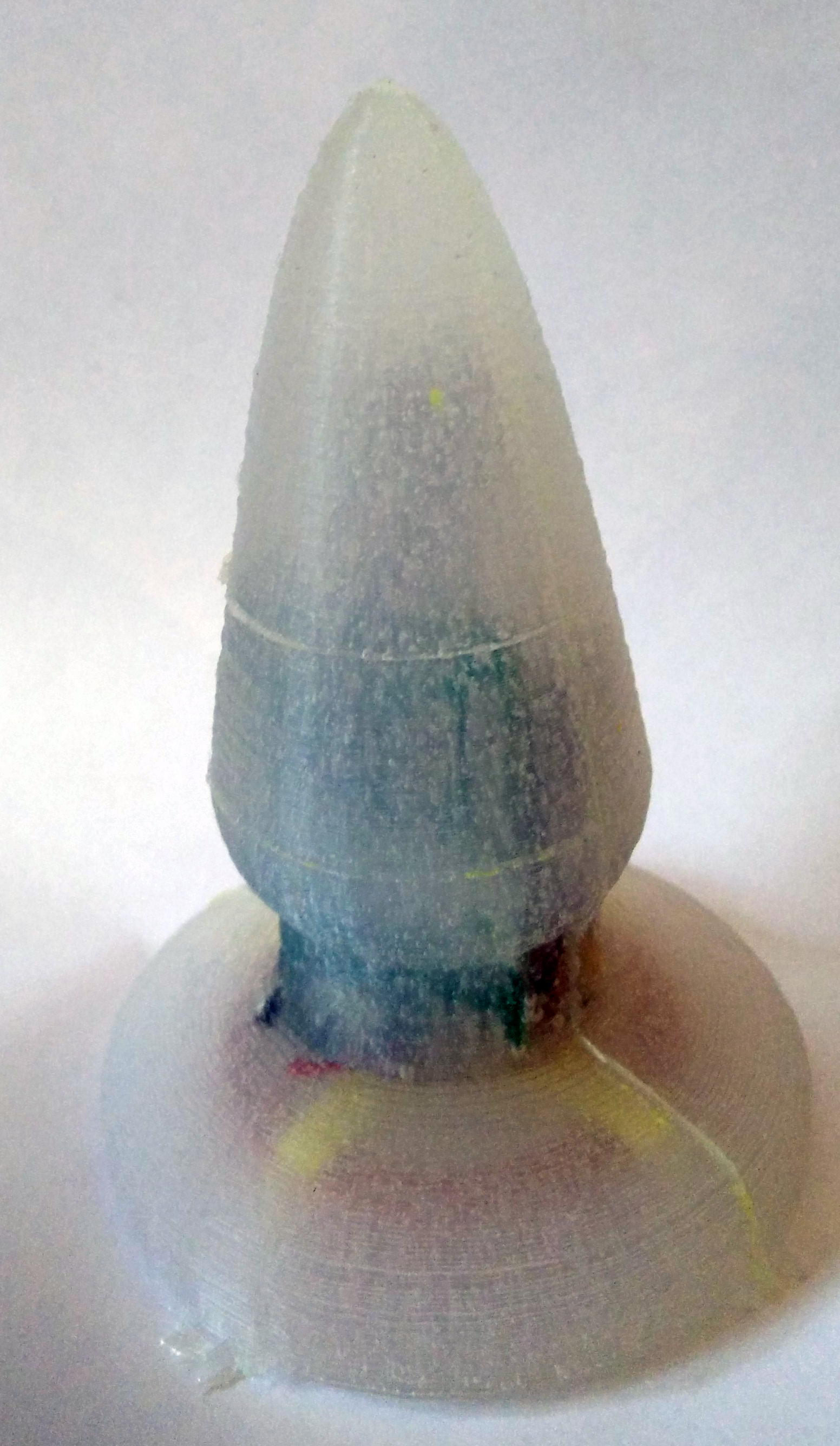
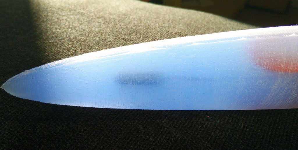
 But you can still see printer artefacts. To overcome this issue you could apply a thicker layer of XTC-3D. If you use a better printer than my daVinci 1.0 the “staircase effect” shouldn’t be a problem at all. Another problem are tiny – sometimes quite large – air bubbles. To remove this air bubbles you need a vacuum chamber. So it is still not perfect, but it works and looks quite good…


 Use some wax to fix little holes in the form where the printer failed. (These are the white spots)