 bodyinteraction designed a lot of vibrating toys, some are usable as massage devices, some are explicit sex toys (vibrator ring, balls), some are experimental (collar). Everyone is motion controlled. If you have more than one they will influence each other remotely, eg. a vibrator and a vibrator ring.

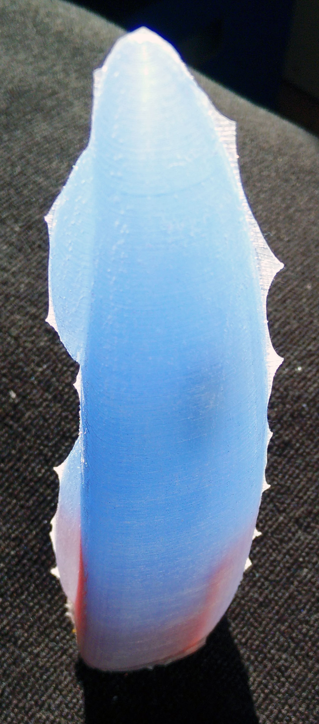
But a device like a classic big vibrator is still missing. So we designed the “fusion” which is approx 19cm long and up to 4+cm in diameter. It is called fusion as the case is made of silicone and 3d printed material (ABS).

We have put the body interaction vibrator development board, motor and battery in a silicone form. There is an on/off switch – so when you travel the vibrator doesn’t wake up when it is moved. And you can charge the battery with a USB micro connector. There is a spacious inlay for the electronics, so it will be easy to get it done.
Pros:
- easy to charge the battery via USB
- on/off switch
- hard handle
- flexible upper part
- large (if you like this)
- ISP interface (“hacker port”) accessible
Cons:
- only the silicone part of the form can be put under water for cleaning
What do you need?
- 200 ml silicone with high shore A rate, eg. shore A 45 from silikonfabrik.de
- optional: special colour for silicone molding
- 3d print of the molding form, inlay and closure
- tinker wire
- body interaction vibrator development board with LiPo and motor (or similar Arduino boards)
- bin for preparing the silicone, something to stir the silicone
How much is it?
- Board, battery, motor: 30$ (buy at Tindie)
- Silicone: 10$
- 3d Prints: less than 5$
Step by step instructions
Step 1: Print out the inlay, the form and the enclosure
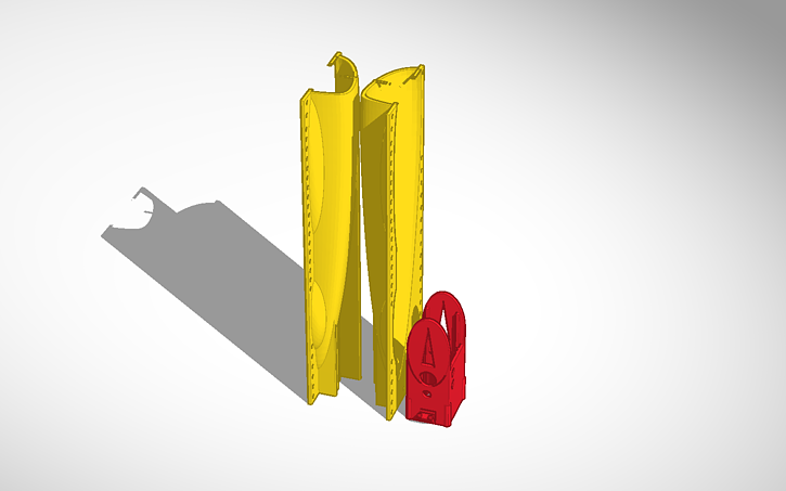
Download as zip-file: Fusion
Download at Thingiverse: http://www.thingiverse.com/thing:1505539
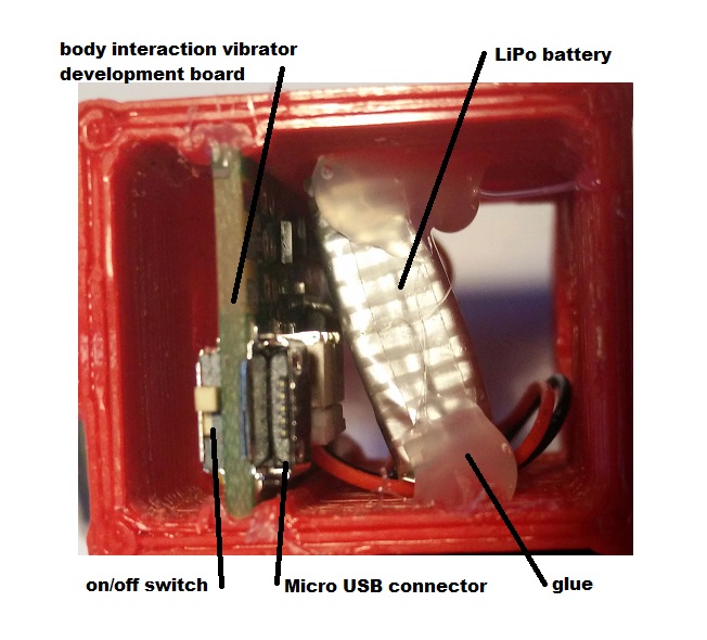
Step 2: Prepare the inlay: Insert the body interaction board and the LiPo battery
The body interaction vibrator development board is inserted into the provided rails. It it doesn’t fit in use a file to remove printing artefacts. Use some glue to fix the board. Then insert the battery and fix it.
Important: The Micro USB connector must be above the upper part of the inlay.
Step 3: fix the wires of the vibration motor
The vibration motor will hang down from the inlay as the inlay will be put in the form upside down. You can influence the position of the motor by shortening the wire or fixing the wire to e.g. to the battery. In this case the wire of the motor was threaded between battery and board. Therefore the motor will be in the middle of the vibrator.

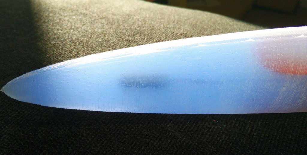
 in the center there is the overmolded vibration motor
Step 5: Prepare the form
Use some tinker wire to “press” both parts of the form tight together. Use some wax to fix little holes in the form where the printer failed. (These are the white spots)

Step 6: Insert inlay into the form
There must be some space between inlay and form for the silicone.
Remark: The two wedge like forms at both sides of the inlay help to hold the inlay. The wedge can be removed after molding.
Step 7: Cast the silicone
Prepare the silicone as the producer recommends. It takes some time to pour the large amount of silicone into the narrow form. The silicone we use must be used within 10 minutes. So start at once after preparing the silicone.
Important: The USB micro connector, the switch and the ISP connector shouldn’t be dashed with silicone. If this happens remove the silicone. Maybe some silicone will remain behind. This can be removed later when the silicone is solid.
The battery is covered with silicone, the USB connecor and switch are not.
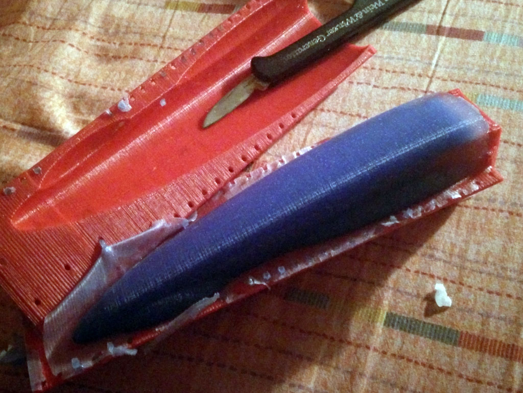
Step 8: Remove the form
Remove the tinker wire. Remove overhanging part of the silicone. Carefully tear both parts of the form away. You can use a knife, but be careful not to “hurt” the vibrator. Remove overhanging silicone at the vibrator. Also remove the two wedge like forms at both sides of the inlay.
Step 9: Install the closure
Now you can put the closure on the inlay. Fix the closure with glue. (Be careful! The USB connector is not very strong.) 


Tinker, share and download from Tinkercad:
form and inlay: https://tinkercad.com/things/b8nQxRn4XWl
closure: https://tinkercad.com/things/dhgtgeaYG0B
Download as zip-file: Fusion
Download at Thingiverse:
http://www.thingiverse.com/thing:1505539